Tie Back
44 Tieback Wall Design and Construction Final Report to the Alabama Highway Research Center Frazier Parker, Jr., Direc
Views 163 Downloads 0 File size 3MB
Recommend stories


- Author / Uploaded
- Panxo Ordenes
Citation preview
44
Tieback Wall Design and Construction Final Report to the
Alabama Highway Research Center Frazier Parker, Jr., Director
Dr. David J. Elton, P.E. James E. Whitbeck
September 24,1997
Table of Contents LIST OF FIGURES ........................................................................................................ iv LIST OF TABLES .......................................................................................................... vi 1 INTRODUCTION .......................................................................................................... 1 1.1 Overview of Report ......................................................................................................... 1 1.2 Anchors ........................................................................................................................... 1 1.2.1 History ..............................................................................................................,......... 1 1.2.2 Basic Description ........................................................................................................ 1 1.2.3 List of Terms ............................................................................................................... 2 1.2.4 Advantages and Disadvantages ................................................................................. 2 1.2.5 Applications ................................................................................................................ 3 1.2.5.1 Temporary Anchors ............................................................................................................... 3 1.2.5.2 Permanent Anchors ................................................................................................................ 4 1.2.6 Alternatives ................................................................................................................. 4 1.3 Wall Facings .................................................................................................................... 4
2 TIEBACKS ................................................................................................................... 8 2.1 Design Considerations ................................................................................................... 8 2.1.1 Site Investigation ........................................................................................................ 8 2.1.1.1 General Considerations ......................................................................................................... 8 2.1.1.2 Rock ....................................................................................................................................... 9 2.1.1.3 Soil .......................................................................................................................................... 9 2.1.1.4 Groundwater .......................................................................................................................... 9 2.1.2 Geotechnical Stability ................................................................................................. 9 2.1.2.1 Introduction to Earth Pressures ........................................................................................... 10 2.1.2.1.1 Lateral Earth Pressure ................................................................................................... 10 2.1.2.1.2 Apparent Earth Pressure Diagrams ............................................................................... 10 2.1.2.1.3 Apparent Earth Pressures .............................................................................................. 14 2.1.2.1.3.1 Sand ........................................................................................................................ 14 2.1.2.1.3.2 Soft to Medium Clay .............................................................................................. 14 2.1.2.1.3.3 Stiff Clay ................................................................................................................ 14 2.1.2.2 Factors of Safety .................................................................................................................. 16 2.1.2.2.1 Factor of Safety with Respect to Strength .................................................................... 16 2.1.2.2.2 Factor of Safety with Respect to Load .......................................................................... 16 2.1.2.2.3 Backca1culated Factors of Safety .................................................................................. 18 2.1.2.2.3.1 Sand .................................................................................................................... 18 2.1.2.2.3.2 Soft to Medium Clay ........................................................................................... 18 2.1.2.2.3.3 Stiff Clay ............................................................................................................. 19 2.1.2.3 Limit Equilibrium Anchor Force Design Procedure ........................................................... 19 2.1.2.3.1 Introduction ................................................................................................................... 19
2.1.2.3.2 Failure Plane Location .................................................................................................. 20 2.1.2.3.3 Simple Failure Surface Analysis ................................................................................... 20 2.1.2.3.4 Using Limit Equilibrium for Design ............................................................................. 25 2.1.2.3.4.1 Internal Stability ..................................................................................................... 25 2.1.2.3.4.2 Global Stability ...................................................................................................... 25 2.1.2.3.4.3 Intermediate Stability ............................................................................................. 29 2.1.3 Anchor Characteristics ...............................................................................................29 2.1.3.1 Types of Anchors ................................................................................................................. 29 2.1.3.2 Tendons ............................................................................................................................... 32 2.1.3.2.1 Types ........................................." .................................................................................... 32 2.1.3.2.2 Design ........................................................................................................................... 32 . 2.1.3.2.2.1 Design Criteria ....................................................................................................... 32 2.1.3.2.2.2 Design for Stress .................................................................................................... 33 2.1.3.2.3 Corrosion Resistance of Unbonded Tendons ................................................................ 33 2.1.3.2.3.1 Introduction ............................................................................................................ 33 2.1.3.2.3.2 Protection Methods ................................................................................................ 34 2.1.3.3 Grout .......................................................................................................... :......................... 35 2.1.3.3.1 Functions ....................................................................................................................... 35 2.1.3.3.2 Composition .................................................................................................................. 35 2.1.3.3.3 Design ........................................................................................................................... 36 2.1.3.3.3.1 Grout-Ground Bond Design ................................................................................... 36 2.1.3.3.3.2 Grout-Tendon Bond Design ................................................................................... 37 2.1.3.3.4 Corrosion Considerations ............................................................................................. 37 2.1.3.3.4.1 Corrosion of Grout ................................................................................................ 37 2.1.3.3.4.2 Corrosion of Tendon by Grout.. ...................................................... ;...................... 37 2.1.3.4 Anchor Head ........................................................................................................................ 38 2.1.3.4.1 Introduction ................................................................................................................... 38 2.1.3.4.2 Corrosion Protection ..................................................................................................... 38 2.1.4 Number, Spacing, and Orientation of Anchors .......................................................... .42 2.1.4.1 Horizontal and Vertical Spacing and Number. .................................................................... 42 2.1.4.2 Orientation ........................................................................................................................... 43 2.1.5 Shear and Moments in Wall .......................................................................................43 2.1.6 Drainage ....................................................................................................................43 2.1.6.1 Need for Drainage ............................................................................................................... 43 2.1.6.2 Common Drainage Methods ................................................................................................ 43
2.2 Installation ......................................................................................................................45 2.2.1 Anchors .....................................................................................................................45 2.2.1.1 Drilling ................................................................................................................................. 46 2.2.1.1.1 Drilling Methods ........................................... ~ ............................................................... 46 2.2.1.1.2 Flushing ......................................................................................................................... 47 2.2.1.1.3 Water Testing of Borehole ............................................................................................ 49 2.2.1.2 Tendon ................................................................................................................................. 50 2.2.1.2.1 Storage and Handling .................................................................................................... 50 2.2.1.2.2 Installation ..................................................................................................................... 50 2.2.1.3 Grout .................................................................................................................................... 52 2.2.1.4 Construction Limitations ..................................................................................................... 53 2.2.1.5 Stressing ............................................................................................................................... 53 2.2.1.5.1 Methods ......................................................................................................................... 53 ii
2.2.1.5.2 Load Monitoring ........................................................................................................... 55 2.2.1.6 Prooftesting .......................................................................................................................... 55 2.2.1.6.1 Stressing Forces ............................................................................................................ 57 2.2.1.6.2 Precontract Tests ........................................................................................................... 57 2.2.1.6.3 On-Site Suitability Tests ............................................................................................... 58 2.2.1.6.4 Acceptance (Proof) Tests .............................................................................................. 58 2.2.1.6.5 Creep .............................................................................................................................. 58 2.2.1.6.6 Testing Program ............................................................................................................ 59 2.2.2 Wall Facing Installation Concerns ..............................................................................59 2.3 Monitoring ...................... ~ ...............................................................................................59 2.3.1 Anchors .....................................................................................................................60 2.3.1.1 Load Monitoring .................................................................................................................. 60 2.3.1.2 Pore Water Pressure ............................................................................................................ 63 2.3.1.3 Earth Pressures .................................................................................................................... 63 2.3.2 Wall Facing ................................................................................................................64 2.3.2.1 Corrosion ............................................................................................................................. 64 2.3.2.2 Drainage ............................................................................................................................... 64 2.3.2.3 Erosion at the Toe ................................................................................................................ 64 2.3.2.4 Movement of the Wall ......................................................................................................... 64 2.3.2.4.1 On-site Methods ............................................................................................................ 64 2.3.2.4.2 Remote Methods ........................................................................................................... 65
3 GEOLOGY OF BIRMINGHAM, AL ............................................................................ 66 3.1 General Considerations .................................................................................................66 3.2 Site Conditions ...............................................................................................................66 3.2.1 Flooding .....................................................................................................................66 3.2.2 Soil and Rock Characteristics ....................................................................................66 3.2.3 Earthquakes and Sinkholes .......................................................................................67 3.3 Rock Formations in Birmingham ..................................................................................67 3.3.1 Knox Group Undifferentiated .....................................................................................67 3.3.2 Ketona Dolomite .................................................................. :..................................... 68
REFERENCES .............................................................................................................. 69 BIBLIOGRAPHY ............................................................................................................ 70
ASTM SPECIFICATIONS FOR STEEL TENDONS ...................................................... 72
iii
List of Figures Figure 1. Typical parts of a ground anchor (from Xanthakos 1991) ......................................................... 2 Figure 2. Wall types (from Xanthakos 1994) ............................................................................................ 6 Figure 3. Typical construction sequence for a slurry wall (from Xanthakos 1994) .................................. 7 Figure 4. Apparent earth pressure (from Schnabel Foundation Company 1996) .................................... 11 Figure 5. Variation in measured lateral earth pressures in braced excavations ....................................... 12 (from Terzaghi and Peck 1967) Figure 6. Schnabel's apparent earth pressure diagram (from Schnabel Foundation Company 1996) ..... 13 Figure 7. Failure pattern assumed for Henkel's method (from Schnabel Foundation Company 1996) ... 15 Figure 8. Failure surface used in limit eqUilibrium analyses of anchored walls (from SchnabeL ......... 17 Foundation Company 1996) Figure 9. Force equilibrium consideration for an anchored wall system (from SchnabeL ..................... 21 Foundation Company 1996) Figure 10. Comparison of method for determining minimum unbonded length, horizontal backfilL ..... 22 (from Schnabel Foundation Company 1996) Figure 11. Comparison of method for determining minimum unbonded length, sloping backfill ............ 23 (from Schnabel Foundation Company 1996) Figure 12. Force equilibrium considerations for anchored wall systems, failure surface in front of ....... 24 bonded length (from Schnabel Foundation Company 1996) Figure 13. Active and passive earth pressure coefficients (from Navy 1982) ........................................... 26 Figure 14. Force equilibrium considerations for anchored wall systems, failure surface ......................... 27 behind the anchor (from Schnabel Foundation Company 1996) Figure 15. Definition of non-dimensional parameters X, A and ~ (from Schnabel .................................... 28 Foundation Companyl996) Figure 16. Requirements for anchor load along the anchor length (base failure) (from SchnabeL ......... 30 Foundation Company 1996) Figure 17. Types of ground anchors (from Hanna 1982) .......................................................................... 31 Figure 18. Tendon tieoff details (from Hanna 1982) ................................................................................. 39 Figure 19. Recommended tolerances at anchor head (from Xanthakos 1994) .......................................... 40 iv
Figure 20. Typical anchor head detail for double protection of strand tendon (from Littlejohn 1986) .... 41 Figure 21. Drainage schemes for retaining walls (from Bowles 1988) ..................................................... 44 Figure 22. Tendon centralizer details (from Xanthakos 1994) .................................................................. 51 Figure 23. Anchor stressing details (from Hanna 1982) ............................................................................ 54 Figure 24. Anchor stressing log (from Hanna 1982) ................................................................................. 56 Figure 25. Schematic view of load disc cell (from Hanna 1973) .............................................................. 61 Figure 26. Monitoring systems for wall (from Xanthakos 1994) .............................................................. 62
v
List of Tables Table 1. Soil filter criteria (from Terzaghi and Peck 1967) ...................................................................... 45 Table 2. Choice of drilling method and machinery to fit pertinent conditions ......................................... 48 Table 3. Drilling rate index for various rocks (from Xanthakos 1991) ..................................................... 49
vi
Tieback Wall Design and Construction 1 Introduction 1.1 Overview of Report This report gives a general overall introduction to ground anchors, also called tiebacks. Specifically, it focuses on anchors which support retaining walls by use of tendons. First, a section is devoted to an introduction to anchors and wall facings. The anchor introduction (Section 1.2) includes a general description of anchors with important terms, advantages and disadvantages, applications of anchors, and alternatives. Wall facings typically used with tiebacks are briefly described in Section 1.3 and advantages and disadvantages of each are discussed. Section 2 is a detailed treatment of tiebacks. Design considerations (Section 2.1) includes discussion of site investigations, a detailed method for determining expected force in a tieback, anchor characteristics, the number and spacing of anchors, and drainage considerations. Also in this section are notes on installation and monitoring of anchored walls. The geology of Birmingham, Alabama, is treated in Section 3. General geological considerations and site conditions and rock formations of the greater Birmingham area are discussed as related to tieback walls. The report concludes with the references and a bibliography. 1.2 Anchors This section includes a brief history of the development of anchors, a description of an anchored system, and a list of terms which are often encountered when discussing tiebacks. 1.2.1 History
The history of anchors may be traced back to the late 1800's. In 1847, Frazer described tests on rod anchors which were installed to support a canal bank. Documentation of the use of screw piles to prevention flotation of floor slabs was described in 1900. However, the Cheurfas dam in Algeria represented the first major application of ground anchors. In 1934, Coyne applied WOOton capacity anchors at 3.5 m (11.5 ft) intervals to stabilize the foundation. After this success and the advent of high-strength steel and improved grouting techniques, ground anchors grew in popularity in several countries in Europe and eventually in the United States (Xanthakos 1991). 1.2.2 Basic Description
Tiebacks (also called ground anchors or simply anchors) are devices used to support retaining walls. A rod, wire, or tendon (cable) is anchored to the ground at one end and to the wall at the other. Anchoring in the ground is typically achieved by boring a hole in the soil or rock and encasing a portion of the wire or rod in a grout mixture. The grout forms a bond with the surrounding soil and tieback and secures the anchor. If a tendon is used, the wire is usually prestressed to a desired tension by hydraulic jacks. The tendon may be inclined at any angle. Design and installation of tiebacks requires specialized methods and equipment and postinstallation monitoring. 1
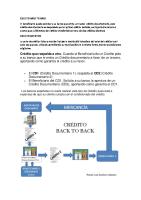
Figure 1 depicts a typical ground anchor and its components. Individual components will be defined briefly in the following section and more completely in Design Considerations (Section 2.1). 1.2.3 List of Terms
A few important terms which are common in discussions of tiebacks are discussed here (Figure 1). 1. The anchor head secures the anchor to the retaining wall and is the location of a jack attachment for prestressing operations. It consists of a mechanism to secure the tendon and a bearing plate to distribute the load to the retaining wall. 2. The anchor tendon is a structure, usually a rod, wire, or cable, which connects the anchor head to the grouted portion of the anchor. 3. The section of tendon which is embedded in the grout is known as the fixed length, while the tendon located between the anchor head and the grout is the free length. 4. Permanent anchors are designed for a life of more than two years, while a temporary anchor is in use for less than two years. 5. A prestressed anchor is the most common type and is tensioned at installation and remains under tension throughout its life. A non-prestressed anchor (also called a dead anchor) is not prestressed at installation. 6. The working load is the force which the anchor will maintain throughout its life. The test load is applied soon after installation to confirm the anchor's integrity, and the lift-off load is the load required to lift the bearing plate from the wall. 1.2.4 Advantages and Disadvantages
This section provides guidance regarding when tiebacks should or perhaps should not be used.
Anchorage _ - - '
Anchored element
Tension member
~-_Grout
Anchor body Drill hole
Figure 1. Typical parts of a ground anchor (from Xanthakos 1991) 2
Advantages of anchored systems for cut slope retaining structures include: (Winterkom 1991): 1. Incorporation of the temporary excavation support system in the permanent facility. 2. Reduction in the amount of excavation and the concrete work required for footings. 3. Elimination of backfilling behind the wall. 4. Elimination of foundation piles to support the wall structure in mountainous areas with unstable slopes or sites underlain by compressible soils. 5. Reduction in quantities of reinforced concrete required for the construction of the retaining wall. 6. Reduction in construction disturbance and right-of-way acquisition, which, in urban sites, may eliminate the need for underpinning nearby structures. 7. Adaptability to different site conditions and soil profiles, allowing for cost-effective use in repair and reconstruction of existing structures. Tiebacks offer other advantages. One is the ability to support a temporary construction excavatfon without the need for cumbersome bracing that obstructs workspace. Anchors may be proof tested to guarantee their capacity. Tiebacks are cheaper than conventional bracing in cuts of more than 4.6 to 6.1 m (15 to 20 ft) and/or widths of greater than 18.3 m (60 ft), and construction is not impeded by cross-bracing. Finally, there is an increase in public safety since less construction area is required (PileBuck 1990). Despite these advantages, anchors are not the solution for all situations. Some disadvantages include (Winterkom 1991): 1. Permanent underground easements are required. 2. In fine-grained soils, effective groundwater drainage systems may be difficult to construct and to maintain. 3. In plastic clayey soils, creep can significantly affect long-term performance and structure displacements. 4. In soft cohesive soils, pull-out capacity of tiebacks cannot be economically mobilized. 5. Durability considerations may impose severe limitations on the use of metallic inclusions in aggressive, corrosive environments. 6. Nearby construction may change soils stresses, decreasing tieback capacity possibly leading to failure. Other disadvantages include potentially increased costs over more conventional walls, an uncertainty regarding their performance over time, and a lack of a standard design procedure (PileBuck 1990). 1.2.5 Applications
Applications of tieback walls vary according to whether the wall is temporary or permanent. This section lists some applications of each type of installation. 1.2.5.1 Temporary Anchors
Temporary anchors are almost always used to support excavations at construction sites. Basements are the most common type of construction utilizing anchors.
3
1.2.5.2 Permanent Anchors
Support of retaining wa1ls are a major use of tiebacks in permanent applications. Although tiebacks are not usua1ly used to support building foundation wa1ls since easements are required from adjacent property owners, there are cases such as a steeply sloping site which make the use of tiebacks attractive. Tiebacks may be used to prevent a landslide or to stabilize soil which has experienced movement. Rock fractures may be stabilized as well. Anchors are often used to support marine structures such as walls at harbors. Fina1ly, tiebacks may be used to repair or alter existing walls and abutments. (PileBuck 1990). 1.2.6 Alternatives
Tiebacks are not a1ways the best solution to a given retaining wa11 project. This section describes several a1tematives to tieback walls. Perhaps the simplest a1temative to tiebacks is to cut the slope back to a less steep angle. One advantage is that this method has been used for many years; therefore, contractors have much experience with the process. The additional materia1 which is removed may be used for fill, and there is no need to acquire a permanent underground right of way. Disadvantages are primarily related to cost. More excavation is needed, and soil/rock must be removed. This method requires more property acquisition at the top of the slope, and this land may not be able to be used for any other purpose. Soil nailing is another option. Soil nailing is similar to tieback construction. It is used in top down construction. Typica1ly, the nails (rods) are drilled and inserted in the soil with facing. Large bearing plates are used. The nail is often posttensioned. This method may a1low for quicker insta1lation and for the insta1lation of a cheaper wa11 facing. However, the method is not widely used in the United States (a1though it is popular in Europe). In addition, insta1lation costs may be higher (Bang 1992). Other options include relocating the project or grouting the slope so it can be cut more steeply. 1.3 Wall Facings There are numerous types of wa1ls which may be used in anchored systems. This section will discuss some of the most common types and provide some advantages and disadvantages of each. For walls which involve concrete cast in place below grade, the construction method is "tremie" concrete. This method involves drilling a hole, filling it with a slurry as it is drilled, and then pouring concrete into the hole through a long tube which reaches to the bottom of the hole. The concrete, which is denser than the slurry, displaces the slurry up and out of the hole. Reinforcing may be placed before the tremie process begins or after, a1though placement in fresh concrete is more difficult. Anchored inclined retaining walls consist of a simple slab of reinforced concrete supported by anchors. These slabs, precast or cast in place, which vary in thickness from 0.3 m (l ft) to 0.6 m (2 ft) or greater, offer excellent flexura1 rigidity and stiffness and may be designed as a two-way member. No embedment is necessary below ground level, there are no constraints on the number or placement of anchors, and little axial load is applied downward. Precast holes may 4
be used to install the tiebacks. Good quality may be obtained even under field conditions (Figure 2a). Cylinder walls are composed of large holes drilled closely together and then filled with concrete. Construction of the drilled shafts proceeds by first installing every other shaft, then repeating the process on every other shaft, often staggered behind the first row. H-piles may be driven in with lagging (wood or concrete) added behind the flanges of the Hpiles as excavation proceeds to create a steel soldier pile and lagging wall (Figure 2d). These walls offer moderate bending resistance and fair watertightness if care is used in construction. Disadvantages include rusting of the steel piles and the possibility that the ground will be hard or contain boulders which precludes pile driving. A steel soldier pile and lagging wall is typically used for temporary installations. Spacing of anchors is usually chosen to match beam and lagging spacing which is typically 2.4 to 3 m (8 to 10 ft). A similar type of wall is formed by soldier piles embedded in concrete. Steel H-piles or concrete piles are driven in as in the previous wall type, and one space at a time is excavated between the piles and filled with concrete. Drilled shafts may be used instead of piles, and reinforcement may be installed in the shafts. Features of the wall include moderate bending resistance and good watertightness. However, the piles are subject to rust, and the ground must allow the piles to be driven in. Closely spaced piles of any type (pipe piles work well) may be used to construct what is typically a temporary wall. Moderate bending resistance is available depending upon the pile material. Ground conditions must be suitable to driving of the piles, and watertightness is poor. As with all walls which contain driven piles, work in congested areas may be limited by available headroom and by noise concerns. The tiebacks are typically attached to a waler that runs horizontally across the piles. Steel sheetpiling offers low bending resistance and fair watertightness if good construction practices are used (Figure 2e). However, rusting of the steel may be a problem, and the soil must be conducive to driving of piles. Limited vertical load capability may limit anchor inclination, but horizontal anchor spacing is not limited since horizontal waling beams (walers) must be installed across entire wall face. to distribute the tieback force across the face of the thin walL Concrete sheetpiling offers the same advantages and disadvantages as steel sheetpiling except for rusting. However, there is the additional disadvantage that cracks may be introduced in the concrete during installation if care is not taken. Diaphragm walls, also called "slurry walls," are formed when concrete is cast into a long slot in the ground (Figure 2 b,c). The slot may be created by excavating one long trench with a special machine and using slurry to keep the trench open, by driving piles into the ground and excavating the panels between them, or by a large machine that augers out the soil and pumps in slurry. Alternatively, the wall sections may be precast, assembled on site, and installed in the trench. These walls offer very good bending resistance and a very good watertightness. Also, they offer excellent vertical load capacity and impose no limitations on anchor spacing or inclination. Figure 3 shows a typical construction sequence for slurry walls.
5
(a) Anchored inclined retaining walls Built of reinforced concrete. Continuous across joints Variable thickness, ranging from 1 to 2 ft or greater Good quality under field control conditions Considerable stiffness and flexural rigidity Can be designed as two-way slab No embedment necessary below base level Axial downward loads relatively small No restraint on anchor spacing, load, or inclination (b)
Cast-in-place diaphragm walls Built of reinforced concrete, usually discontinuous panels Thickness up to 3 ft or greater Good quality under field control conditions Considerable stiffness and flexural rigidity Embedment necessary below base level High capacity in vertical loads Usually 2 anchors per horizontal row each panel No restraint on anchor load and inclination
(c) ?t.=.=_--=-_-~-
Precast diaphragm walls Factory-built reinforced concrete panels Usual thickness 18-24 in Adequate stiffness and flexural rigidity Embedment necessary below base level Adequate capacity in vertical loads Usually 2 anchors per horizontal row each panel No restraint on anchor load and inclination
(d)
-----
(e)
Soldier piles with lagging Predriven steel beams with lagging; occasionally placed in boreholes Relatively flexible; beam embedment necessary Wall is not watertight Limited capacity in vertical loads restricting anchor force and inclination; anchor spacing to conform to beam spacing and commercial lagging size, usually 8- [0 ft Sheet pile wall
--~.--
Driven in suitable ground; generally adequate groundwater control; restricted to soft soils Very flexible wall with limited stiffness Limited capacity in vertical load restricting anchor force and inclination Waling beam necessary at each horizontal anchor row Horizontal anchor spacing not restricted
Figure 2. Wall types (from Xanthakos 1994) 6
Concreted panel
Concreted panel Slurry level
Bentonite slurry
Bentonite slurry
(a)
(b)
Steel tube
Tremie pipes
[QJ
Fresh concrete
~~d![C:::::::::::j () (c)
(d)
Figure 3. Typical construction sequence for a slurry wall (from Xanthakos 1994) 7
2 Tiebacks 2.1 Design Considerations 2.1.1 Site Investigation
A thorough investigation of a proposed site for the use of anchors is crucial to the success of the project. Data gathered from the site investigation will be used to determine the placement of anchors, their capacity, materials to be used, corrosion protection required, and the method of installation. Since every construction site has different ground conditions even at the same site, specific site investigation programs must be determined by an engineer. In addition, the scope of the construction project itself will play a role in determining the site investigation program. This section provides some general considerations with regard to site investigations, and particular considerations for investigating rock, soil, and groundwater. 2.1.1.1 General Considerations
Throughout the planning of a site exploration, the engineer should be aware of several key factors in the design of anchors. These include the behavior of anchors under load, construction methods and the disturbance they may cause to the ground, variation of ground conditions, effects of construction on surrounding property, and environmental concerns such as freezing. Three basic principles of investigation should be kept in mind: scope of the project, accessibility of the ground where the anchors will be formed, and behavior of soil andlor rock under the intense stress that an anchor produces (Hanna 1982). The initial step in a site investigation is usually known as a "desk study." Readily available information such as maps are studied to determine if further investigation is warranted or if the project is not feasible. Maps and photographs of a proposed site provide information regarding site topography. Geologic and soil survey maps may be used to predict the type of soil and rock which may be encountered and may provide clues to earthquake probability. Information regarding groundwater may be obtained from simple tests. Finally, history of previous construction projects may be used as a guide if such information is available. An important component of the site investigation is to determine if any of the anchors will be placed on adjoining property. If this is the case, permissions must be obtained from the landowners. Also, the location of underground utilities, foundations, and other structures must be determined, and the feasibility of construction with regard to disturbances to local traffic and surrounding buildings must be studied. Rock, soil, and groundwater investigations, the topics of the next three sections, are usually carried out by drilling exploratory holes at the site. Since many anchors are installed horizontally while most boreholes are drilled vertically, more boreholes will be required for horizontal anchors than for vertical ones. In addition, anchors are very sensitive to variations in local ground conditions. Other conditions which may lead to the need for more boreholes include sloping ground or very long anchors.
8
2.1.1.2 Rock
The best investigation method for rock is drilling cores. The rock samples may be analyzed in a lab for composition, unit weight, strength, adhesion to grout, and coefficient of friction with steel (Robst 1983) as well as modulus of elasticity, uniaxial compressive strength, interfaces between strata, and the amount and condition of water in the rock (Xanthakos 1991). Corings provide valuable data regarding the stratification of rock layers, the structural integrity of the rock (faults, fissures, failure planes), and strength of the rock. Boreholes may be pressure tested to detect the presence of faults and as a guide for grout design. Rock should be sampled with continuous core recovery methods which require a core not less than 75 mm (3 in) in diameter. Very weak rock may be investigated with a SPT to gain a relative idea of the in situ qUality. For soft rock, durability studies should be made. Rock should be graded according to a standard index such as Rock Quality Designator. 2.1.1.3 Soil
Soil investigations should attempt to determine the composition and mechanical properties of the soil as well as the variation of these properties throughout the construction site. Soil samples are gathered for lab analysis which should include composition, shear strength, cohesion, particle size, liquid and plastic limits, and angle of internal friction. Boreholes may be used for determination of the soil limit stress and for groutability tests .. In addition, the construction of the testing boreholes may provide an indication of how easily the anchor boreholes may be constructed. Samples may be obtained using any of a number of standard tools such as the Standard Penetration Test (ASTM D1586-84) and Shelby tubes. Samples should be collected at vertical intervals of about 1.5 m (5 ft) (Xanthakos 1991) or wherever a change in soil conditions is suspected. The CPT or SPT may be used to gather soil density data. A field vane or Dutch Cone may be used in cohesive soil to gauge soil strength. 2.1.1.4 Groundwater
Groundwater levels should be monitored over the long term. Samples of groundwater should be tested for possible corrosive effects on tendon steel and/or grout. Levels should be monitored to determine corrosion protection required, effect of groundwater on soil properties, and hydrostatic forces which may act upon the retaining wall. The best method is by the use of piezometers. Water infiltration may be estimated during construction from a comparison of the amount of drilling fluid pumped into a borehole to the amount which flows out or by field permeability tests. Also, detailed data should be gathered during construction of anchor boreholes in regard to drilling rate and difficulty and condition of the drill spoil. 2.1.2 Geotechnical Stability
The first step in designing ground anchors is determining the force that will be applied to the wall by the soil. This section details a procedure for evaluating the horizontal force exerted on a wall by the soil behind it.
9
2.1.2.1 Introduction to Earth Pressures
The basic concept regarding forces acting on a retaining wall is that of lateral earth pressures. Various methods of estimating these forces have been developed, ranging from simple to complex. This section will provide a brief introduction to these methods as background for the presentation of a design procedure. 2.1.2.1.1 Lateral Earth Pressure Two primary methods of estimating lateral earth pressure are used today. Coulomb presented a method in 1776 which assumed a planar failure surface and considered friction between the wall and the soil. Rankine's theory of 1857 was based on the condition at which every soil particle is on the verge of failure and neglected wall friction in estimating both the magnitude and direction of the force. Both theories deal with three different conditions defined by the movement of the wall: active, when the wall has moved slightly outward and allows interparticle soil friction forces to develop; passive, when a wall has moved into the soil mass; and at-rest, which occurs when the wall has not moved in either direction. In both methods, forces are determined by multiplying the vertical pressure (using terms which account for the weight of the soil and the height of the wall) by a coefficient known as the lateral earth pressure coefficient. For a smooth vertical wall with level backfill, both theories yield a similar result for this coefficient for the active and passive cases. Other theories that assume a log spiral shape for the failure surface have been developed. However, the results are very similar to those of the much simpler Rankine methods for the active case. Therefore, the design method presented in this report will be based on the Rankine method and on apparent earth pressure. 2.1.2.1.2 Apparent Earth Pressure Diagrams An alternative way of estimating the pressures exerted on a wall by surrounding soils is by the use of apparent earth pressure (AEP) diagrams. Figure 4 shows the apparent earth pressure diagrams for three different types of soils. These apparent earth pressure diagrams were developed based upon field measurements rather than theory. Measurements were made of the forces exerted on struts which were supporting a retaining wall as excavation proceeded. The forces in the struts were then divided by the area of wall which they supported to construct the apparent earth pressure diagram. These experiments and similar ones have shown that total forces predicted by the Coulomb and Rankine methods are very close to the observed forces. However, the distribution of these forces along the wall is different. The classical methods yield a triangular pressure distribution, with lower stresses near the top of the wall and higher stresses at the bottom. Actual field studies show variations from this (Figure 5). Schnabel (1996) suggests using one apparent earth pressure diagram for all designs (Figure 6), stating that "Schnabel Foundation Company has successfully used this diagram to design thousands of anchored excavation support systems and anchored walls in sands, clays, and mixed soil profiles. " Given the close results of the simple and more complex methods, the simpler Rankine method of active earth pressures will be used as the baseline for earth pressure design. A simple approach allows a more general formulation of the boundary condition problem. Also, changes in 10
Sands
Soft to Medium Clays
Stiff-Fissured Clays
I}
Struts
I} 0.25H
0.25 H ~
H
--*_ r --*_ tH
I-' I-'
~ ~O.65
Ka y H-l 2
~1.0 Ka y H ~
~0'4 y H O.4y H
Ka = tan (45 - /2)
Ka -1
______ 4su
yH
b)
c)
Figure 4. Apparent earth pressure (from Schnabel Foundation Company 1996)
to--l
-----
Apparent Earth Pressure - /00 fbi ft 2 mom mom ~ 0 m
o m o SIA ~ 10 I ...... tv
•
-
I
~
0
10
20
i
06£
~
::E: 20 ~ ~ 30 40
~
Chicago
Chicago
S/;ellhaven
Vater/and 3 Oslo
Tokyo-M
Figure 5. Variation in measured lateral earth pressures in braced excavations (from Terzaghi and Peck 1967)
o.L
~
H
H2
tO.2H
H3
Figure 6. Schnabel's apparent earth pressure diagram (form Schnabel Foundation Company 1996) 13
conditions such as wall geometry, strength properties, and groundwater may be evaluated much more quickly. 2.1.2.1.3 Apparent Earth Pressures
The Rankine method of active earth pressure utilizes a coefficient multiplied by terms for vertical pressure to estimate the lateral pressure. Differing soils have characteristic equations for this coefficient. The equations for the AEP coefficient for the three types of soil (sand, soft to medium clay, and stiff clay) in Figure 4 will be introduced here and expanded in the following sections. 2.1.2.1.3.1 Sand
Sand, a cohesionless material, has the following equation for the Rankine coefficient of active earth pressure (Equation 1) for level backfill and a failure surface through the bottom of the cut [1]
2.1.2.1.3.2 Soft to Medium Clay
Soft to medium clays are soils which have a ratio of yH/s u greater than about six, where y = unit weight of the soil, H = height of the wall, and Su = the undrained shear strength of the clay. The corresponding equation for the Rankine active earth pressure coefficient if the failure is through the bottom of the cut is given as Equation 2. [2] If the failure plane passes below the bottom of the cut as shown in Figure 7; Henkel's (1971) method should be used:
J
4su M d ( 1-(2+n)Sub K =1--+2",2A yH H yH
[3]
It should be noted that if the soil at the base is stiff enough to force a failure plane to pass through the bottom of the cut, the larger of the values produced by Equation 2 and Equation 3 should be used. 2.1.2.1.3.3 Stiff Clay
Stiff clay is a soil which has a yH/s u ratio less than four. Results of Terzaghi (1996) report that the apparent earth pressure distribution is a total force proportional to 0.75fyH2 , where f is between 0.2 and 0.4 (see figure 4). 14
H ..... u.
Su
....••.•••.••.••••....•••.•............
d
sub
Figure 7. Failure pattern assumed for Henkel's method (from Schnabel Foundation Company 1996)
--------
---------~-------
-~-----.----------------
2.1.2.2 Factors of Safety
There are two basic types of factors of safety (FS) used in these analyses, either based upon strength or based upon load. These factors of safety must occasionally be backcalculated. Each of these cases is defined and explained below. Typical FS values commonly used to design anchors are provided. In the following discussion of factors of safety, the forces predicted by the Rankine method are assumed to be the actual earth forces which are acting upon the wall. The apparent earth pressures (from the AEP diagrams) are used in the design of the wall. The AEP diagrams estimate larger forces than does the Rankine method; therefore, a factor of safety is established as the ratio of P AEP to PAR. 2.1.2.2.1 Factor of Safety with Respect to Strength
The factor of safety (FS) with respect to strength is defined as the ratio of soil strength available to the soil strength required for stability (mobilized strength). For soils with friction, the basic equation is F
S
tan¢avail
strength
=t
[4]
",
an'l'mob
For soils with cohesion, the corresponding equation is avail FSstrength =C-
[5]
C mob
These equations are applied when the failure surface passes below the structural wall components and behind the ground anchors or when the failure surfaces intersect the anchors themselves or other structural components Figure 8. Common values for this type of FS range from 1.1 to 1.5. Selection of a FS for use in the design depends on a number of considerations, including the importance of the wall, consequences of failure, and economics. 2.1.2.2.2 Factor of Safety with Respect to Load
The basic definition of this FS is the ratio of the load applied to the soil by the anchors to that load required by the soil for stability (Equation 6) FS[oad
loadapplied load reqd
= -----''-'-----
[6]
This FS is applied when the failure surface passes in front of the anchor as illustrated in Figure 8. In this case, the anchor load affects the stability of the soil since its force is acting external to the failure wedge. Typical values range from 1.2 to 2.0.
16
----------
- - - - - - - - - - - - - - - - - - - - - - - - - - - - - - - - - - - - - - - - - - -------
..... -..l
Figure 8. Failure surface used in limit eqUilibrium analyses of anchored walls (from Schnabel Foundation Company 1996)
2.1.2.2.3 Backcalculated Factors of Safety
Factors of safety with respect to load (FSload) may be backcalculated by comparing the ratio of forces predicted by the apparent earth diagrams to those predicted by the Rankine method of active earth pressures and assuming the Rankine method produces a FS=1. To calculate FS with respect to strength, a value for the mobilized angle of soil friction,