Stab Calc
DETAILED TRANSPORT CALCULATIONS Client dependant Client Name Client : Project name Project : Project description :
Views 116 Downloads 0 File size 79KB
Recommend stories


- Author / Uploaded
- juriesk
Citation preview
DETAILED TRANSPORT CALCULATIONS
Client dependant
Client Name
Client :
Project name
Project : Project description :
Project Description
Reference number :
466023-9-K15
Load description :
Diesel engine
Length : Width : Height : Weight : Location :
Client approval (stamp/sign):
Client remarks :
Authorized name: The Works Int dependant
Project/file number :
0
23-Aug-03
For Bid
Marco J. van Daal
Revision
Date
Reason for issue
Project Manager
StabCalc
Stability calculations for Hydraulic Platform Transporters
Remarks Page: 1/4
TRANSPORT CALCULATIONS INPUT:
Diesel engine ENG. SPMT Single 12 Liner
Trailer configuration
1500 mm 2430 mm
No.
22e035
0
(Ll) = (Lh) =
12472 mm 6432 mm
trailer heigth trailer width
(Th) = (Tw) =
trailer length trailer axle lines trailer CG (y) trailer weight 3 or 4 point susp.
(Tl) = (n) = (CG) = (Wt) = (p) =
axle base axle centre height
(Sa) = (Ah) =
1450 mm 363 mm
load transparancy factor additional weight
(Tf) = (Wa) =
1 0.0 mTon
max axle pressure trailer speed
(Ap) = (V) =
17.0 mTon 5.00 km/h
gravitation average wind pressure
(g) = (Wp) =
9.81 m/sec² 11.8 kg/m²
curve impact Mu steel/wood transverse road gradient longitudinal road gradient chain capacity
(Ci) = (Mu)= (Mgt) = (Mgl) = (cc) =
2.00 0.20 1.00 3.00 5.00
16800 12 1200 55.0 3
max. acceleration (a) = max. decceleration (d) = Axles suspended (Sn) = Safe hydr. stability angle (Shsa) = Safe structural stab. angle (Sssa) =
0.50 2.50 8-0-8-8 8.00 5.00
load length load height (incl. beams)
Rev.
mm Nos. mm mTon point
load width load weight height CG (y) (incl. beams) transverse CG longitudinal CG
m/sec² m/sec² Nos. deg. deg.
(Lw) = (Wl) = (CGh) = (CGt) = (CGl) =
5516 170.0 1500 10 10
mm mTon mm mm out mm out
% deg. deg. mTon each
Note: All assumptions are worst case
LASHING CALCULATION Acceleration Forces on Max Ground Slope:
F N R1
= (Wl + Wa) * sin ( Mgl )
= (((Wl + Wa) * a ) / g) + F - ( Mu * N )
= = =
C1
= R1 / cc
=
= (Wl + Wa) * cos ( Mgl )
( If R1 negative, no chains required )
8.90 mTon 169.77 mTon -16.4 mTon 0 chain(s) required in front direction
Decceleration Forces on Max Ground Slope:
F N R2
= (Wl + Wa) * sin ( Mgl )
= (((Wl + Wa) * d ) / g) + F - ( Mu * N )
= = =
C2
= R2 / cc
=
= (Wl + Wa) * cos ( Mgl )
( If R2 negative, no chains required )
8.90 mTon 169.77 mTon 18.3 mTon 4 chain(s) required in rear direction
Chains required for lashing:
4 chain(s) required
= C1 + C2
Y
Single system, load and trailer (Y/N)? :
12 chain(s) required
= Wt / cc
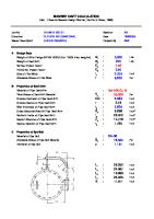
GROUND BEARING PRESSURE CALCULATION Weight Trailer + Load + Add. Weight = Wtot Load / line Load / axle Load / tyre Load / width of tire Ground Pressure StabCalc
225.0 225.0 225.0 4.7
mTon over mTon over mTon over mTon over
= 12 24 48 12
Lines Axles Tyres inch
= = = = =
225.0 mTon 18.8 9.4 4.7 0.39 5.5
Stability calculations for Hydraulic Platform Transporters
mTon mTon mTon mTon/inch = mTon/m²
860.4 lbs/inch
Page: 2/4
STABILITY ON HYDRAULICS CALCULATION CGtoth
= ((Wt*CG) + ((Wl+Wa)*(CGh+Th)))/Wtot
=
2560 mm
CGtott CGtotl
= ((Wl + Wa) * CGt) / Wtot = ((Wl + Wa) * CGl) / Wtot
= =
8 mm 8 mm
Ltri
= SQRT((0.5*Sa)² + (0.5*Tl)²)
=
8431 mm
(C.O.G. of Trailer + Load + Beams) out of center out of center Length of stability triangle
Longitudinal stability angle
Aminl Lng. Cam
= (Tl/2 - 0.5*GroupD - CGtotl) = Aminl / (CGtoth - Ah)
= =
2792 mm 1.2707
Lng. Grad
= arctan (Lng. Cam.)
=
51.8 deg. OK !
CGtotl towards 2 groups (C&D) Longitudinal Stability Camber Max. longitudinal Gradient on Stability
Transverse stabitily angle
Amint
= ((0.5*Tl-Aminl)*sin(0.5*Sa/Ltri))-CGt
=
476 mm
Tr. Cam. Tr. Grad
= Amint / (CGtoth-Ah)
= =
0.2168 12.2 deg. OK !
= arctan (Tr. Cam.)
CGtott towards groups (A&D) Transeverse Stability Camber Max. Transverse Gradient on Stability
STABILITY ON STRUCTURE CALCULATION CGtoth CGtott CGtotl
= ((Wt*CG) + ((Wl+Wa)*(CGh+Th)))/Wtot
Fwt Mwt Fwl
= Wp * (Transverse Load Surface * Tf)
Mwl Mt
= Fwl * ((0.5 * Lh) + Th)
Ml Mci Ma/d Mroadl
= CGl * (Wl + Wa)
= tan(Mgl)*(CGtoth-Ah)*Wtot
= = = =
Mroadt
= tan(Mgt)*(CGtoth-Ah)*Wtot
=
= ((Wl + Wa) * CGt) / Wtot = ((Wl + Wa) * CGl) / Wtot
= Fwt * ((0.5 * Lh) + Th) = Wp * (Longitudinal Load Surface * Tf)
= CGt * (Wl + Wa)
= Ci * Wtot * (CGtoth - Ah) = (( Wtot * d ) / g ) * (CGtoth - Ah)
= = =
2560 mm 8 mm 8 mm
= = =
1.14 mTon 5.36 mTon * m 0.50 mTon
Transverse Wind Force
= =
2.37 mTon * m 1.70 mTon * m
Longitudinal Wind Moment
1.70 9.89 126.00 25.91
C.O.G. of Trailer + Load + Beams Transverse out of center Longitudinal out of center
mTon * m mTon * m mTon * m mTon * m
8.63 mTon * m
Transverse Wind Moment Longitudinal Wind Force
Moment due to transverse loadoffset Moment due to longitudinal loadoffset Curve Impact Moment on Trailer Acceleration / Deccelaration Impact Moment due to road gradient Moment due to road gradient
Longitudinal stability on strength
Group A
9.38 2.32
Group B
11.70 OK ! Lng. Cam Lng. Grad
0.00 0.00
Group C
0.00 OK !
= ((Ap*0.5*Tl/Fmax*2)-(0.5*Tl/2))/(CGtoth-Ah) = arctan (Lng. Cam.)
= =
9.38 1.16
Group D
10.54 OK ! 0.8667 40.9 deg. OK !
9.38 mTon / axle 1.16 mTon / axle (due to moments) 10.54 mTon / axle (Fmax.) OK ! Longitudinal Stability Camber Max. Longitudinal Gradient on strength
Transverse stability on strength
Group A
Tr. Cam. Tr. Grad
9.38 0.00 9.38 OK !
Group B
0.00 0.00 0.00 OK !
= ((Ap*Sa/Fmax*2)-(0.5*Sa))/(CGtoth-Ah) = arctan (Tr. Cam.)
Group C
= =
9.38 Group D 2.20 11.58 OK ! 0.1544 8.8 deg.
9.38 mTon / axle 2.20 mTon / axle (due to moments) 11.58 mTon / axle (Fmax.) OK ! Transeverse Stability Camber Max. Transverse Gradient on strength
OK ! StabCalc
Stability calculations for Hydraulic Platform Transporters
Page: 3/4
OVERALL CONCLUSION: •
STABILITY LIMIT:
8.8
deg.
•
LASHING CHAINS REQUIRED:
12
Nos.
•
GROUND BEARING PRESSURE :
5.5
mTon/m²
STABILITY ON STRUCTURE
GENERAL SITUATION: Transverse Direction
Stability arm 3-point suspension
CGtott Group A
Group B
Transverse: A or B Longitudinal: E or F
4-point suspension Transverse: C or D
Axle Distance
Longitudinal: G or H
G E
CL
A B D
CGtotl
Tl
C Longitudinal Direction
C.O.G. F H
CL
Group D
Group C
Sa
Tw
Note 1: General situation, drawing does not adapt to input- and calculated values. Note 2: Group A and B should have less axles than Group C and D if need be. Note 3: In case of 3-point suspension Group B = 0.
NOTES: • • • • StabCalc
The transverse transporter gradient will be kept within +4 and -4 degrees with the road by the transporter operator. Calculations are based on transporter driving in normal mode, not in transverse mode. All assumptions are highly estimated, and therefor not allways according to the drawings. Road gradient is included in lashing and structural calculation but not in hydraulics calculation. Stability calculations for Hydraulic Platform Transporters
Page: 4/4