Puente Viga Losa-2
PUENTE VIGA Y LOSA DE CONCRETO ARMADO DISEÑO SUPERESTRUCTURA DEL PUENTE BLANCO CARRETERA METAL (San Martín) - MARCOS (La
Views 185 Downloads 6 File size 820KB
Recommend stories


- Author / Uploaded
- Benjamin Lopez Cahuaza
Citation preview
PUENTE VIGA Y LOSA DE CONCRETO ARMADO DISEÑO SUPERESTRUCTURA DEL PUENTE BLANCO CARRETERA METAL (San Martín) - MARCOS (La Libertad)
Datos de Diseño de la Superestructura: Sección Sobrecarga vehicular
Curso: PUENTES
= =
Constante HL-93
Luz del tramo Número de vías Ancho de calzada Ancho de veredas Espesor del asfalto Altura de sardinel Espaciamiento entre vigas Longitud losa en voladizo Resistencia concreto F'c Fluencia del acero Fy Recubrimiento del acero
L= Nv = Ac = Av = = = Ls = Lv = = =
20.00 m. 2 vías 7.20 m. 0.65 m. 0.05 m. 0.20 m. 2.70 m. 1.55 m. 280 Kg/cm² 4200 Kg/cm² 4.00 cm.
Docente: Ing. Luis M. Peralta Ruiz
1.- PRE-DIMENSIONAMIENTO 1.1.- Altura de la viga. hmín = 0.070*L
Usar :
1.2.-
hmín =
h
= 1.40 m.
(Tabla 2.5.2.6.3-1 AASHTO, pág. 2-15)
1.40 m.
Ancho de la viga. Dado:
b = 0.0157 ∗ Ls *L
Ls = 2.70 m. L = 20.00 m.
b = 0.52 m. Usar : 1.3.-
b
= 0.50 m.
Espesor de la losa. Criterios: a) Losa de tablero de concreto. tmín = 0.175 m.
(Artículo 9.7.1.1 AASHTO, pág. 9-8)
b) Criterio del puente losa.
tmín
=
Ls + 3000 30
tmín
(Tabla 2.5.2.6.3-1 AASHTO, pág. 2-15)
165 mm.
Dado:
Ls = 2700 mm.
= 190 mm.
c) En voladizos de tablero que soportan barreras de concreto (sardinel de vereda + barandas) (Artículo 13.7.3.1.2 AASHTO, pág. 9-8)
tmín Usar :
Curso: PUENTES
t
= 200 mm.
= 0.20 m.
↔ El mayor valor a), b) y c).
Docente: Ing. Luis M. Peralta Ruiz
2.- DISEÑO DE LA LOSA
El acero principal Asp es perpendicular al tráfico. Concordante al Art. 9.5.3 del AASHTO, no es necesario investigar por Fatiga. (Tabla 3.4.1-1 AASHTO, pág. 3-16) Los criterios LRFD aplicables serán: Resistencia I : Servicio II :
U= U=
h [1.25*DC + 1.50*DW + 1.75*(LL+IM)] h [1.00*DC + 1.00*DW + 1.30*(LL+IM)] Al usar factores de multiplacidad g valores máximos h=hDhRhI = 0.95
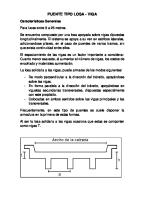
El ancho efectivo "E" de aplicación de un eje del camión es independiente del número de vigas. Por ejemplo el presente diseño también puede tener 04 vigas:
-157.06
2.1.- CALCULO DE MOMENTOS EN LA LOSA. 2.1.1.- Momento por peso propio (Kg-m). wlosa = t x 1.00m x 2500Kg/m³ = 500.00 Kg/m Momento negativo en apoyo central = 157.06 Kg-m
Curso: PUENTES
Docente: Ing. Luis M. Peralta Ruiz
2.1.2.- Momento por peso vereda y baranda (Kg-m).
wvereda =
0.25 x 1.00 x 2500Kg/m³ = 625.00 Kg/m Pbaranda = 1.00m x 100Kg/m = 100.00 Kg.
wasf. = easf x 1.00 x 2250Kg/m³ =
2.1.3.- Momento por peso del asfalto (Kg-m).
112.50 Kg/m
2.1.4.- Momento negativo en la losa por S/C en la viga interior (Kg-m). Para 01 metro de ancho de losa, el momento se divide entre el ancho de faja equivalente. E − = 1.22+0.25 Lsn =
(Tabla 4.6.2.1.3-1 AASHTO, pág. 4-22)
1.77 m.
Dado: Lsn = Ls-b = 2.20 m. IM = 0.33 De los esquemas de cálculo de momento:
M− =
Curso: PUENTES
M(LL+IM) E
=
3,086.30 Kg-m
⬚ MLC = ⬚ MLE = ⬚ MIM =
3,685.44 Kg-m 561.12 Kg-m 1,216.20 Kg-m
}
⬚ M(LL+IM) =
5,462.76 Kg-m
Docente: Ing. Luis M. Peralta Ruiz
Momento por eje posterior del Camión AASHTO:
Momento por carga distribuida en el carril AASHTO:
Curso: PUENTES
Docente: Ing. Luis M. Peralta Ruiz
2.1.5.- Momento negativo en la losa por S/C en la viga exterior (Kg-m). Para 01 metro de ancho de losa, el momento se divide entre el ancho de faja equivalente. E − = 1.14+0.833 X =
(Tabla 4.6.2.1.3-1 AASHTO, pág. 4-22)
1.64 m.
Dado: X = Lv - Av - 0.30 = 0.60 m. IM = 0.33 De los esquemas de cálculo de momento: ⬚ MLC = ⬚ MLE = ⬚ MIM =
M− =
M(LL+IM) E
=
4,440.00 Kg-m 675.45 Kg-m 1,465.20 Kg-m
}
⬚ M(LL+IM) =
6,580.65 Kg-m
4,013.08 Kg-m
Momento por eje posterior del Camión AASHTO:
Curso: PUENTES
Docente: Ing. Luis M. Peralta Ruiz
Momento por carga distribuida en el carril AASHTO:
2.1.6.- Momento positivo en la losa por S/C en tramo interior (Kg-m). Para 01 metro de ancho de losa, el momento se divide entre el ancho de faja equivalente. E + = 0.66+0.55 Lsn =
(Tabla 4.6.2.1.3-1 AASHTO, pág. 4-22)
1.87 m.
Dado: Lsn = Ls-b = 2.20 m. IM = 0.33 De los esquemas de cálculo de momento: ⬚ MLC = ⬚ MLE = ⬚ MIM =
M− =
M(LL+IM) E
=
3,428.69 Kg-m 670.36 Kg-m 1,131.47 Kg-m
}
⬚ M(LL+IM) =
5,230.52 Kg-m
2,797.07 Kg-m
Momento por eje posterior del Camión AASHTO:
Curso: PUENTES
Docente: Ing. Luis M. Peralta Ruiz
Momento por carga distribuida en el carril AASHTO:
2.1.7.- Resumen de Momentos de flexión y aplicando LRFD: Utilizando la Tabla 3.4.1-1 AASHTO, pág. 3-16 MOMENTOS NEGATIVO EN LA LOSA (APOYO INTERIOR) CARGA
MOMENTOS NEGATIVO EN LA LOSA EN VOLADIZO CARGA
g
MOMENTO Kg-
m.
Resistencia I Peso propio (DC) -600.62 1.25 Vereda+Baranda (DC) -652.66 1.25 Asfalto (DW) -45.56 1.50 Camión (LL+IM) -4,013.08 1.75 -8,224.94 Momento negativo en voladizo =
Servicio II 1.00 1.00 1.00 1.30 -6,190.05
g
MOMENTO
Kg-m.
Resistencia I Peso propio (DC) -157.06 1.25 Vereda+Baranda (DC) 322.48 1.25 Asfalto (DW) -79.60 1.50 Camión (LL+IM) -3,086.30 1.75 Momento negativo interior = -5,047.97
Servicio II 1.00 1.00 1.00 1.30 -3,730.05
MOMENTOS POSITIVO EN LA LOSA (TRAMO INTERIOR) CARGA
MOMENTO
Kg-m.
Resistencia I Peso propio (DC) 100.08 1.25 Vereda+Baranda (DC) 0.00 1.25 Asfalto (DW) 39.98 1.50 Camión (LL+IM) 2,797.07 1.75 4,825.94 Momento positivo tramo interior = Resistencia I : Servicio II :
Curso: PUENTES
U= U=
g Servicio II 1.00 1.00 1.00 1.30 3,587.44
h [1.25*DC + 1.50*DW + 1.75*(LL+IM)] h [1.00*DC + 1.00*DW + 1.30*(LL+IM)] Al usar factores de multiplacidad g valores máximos h=hDhRhI = 0.95
Docente: Ing. Luis M. Peralta Ruiz