2 2 1 4
Packet Tracer – Simulating IoT Devices Topology Objectives Part 1: Build the Circuit Place the components in the Log
Views 168 Downloads 2 File size 496KB
Recommend stories


- Author / Uploaded
- Ralph
Citation preview
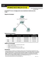
Packet Tracer – Simulating IoT Devices Topology
Objectives Part 1: Build the Circuit
Place the components in the Logical Workspace
Connect the components
Part 2: Program the Single Board Computer (SBC)
Run the default program
Modify the default program
Background / Scenario Packet Tracer has evolved to simulate IoT devices. This tutorial will guide you through the process of placing components in the Logical Workspace, connecting the components, and then programming the single-board computer (SBC) to control them.
Required Resources
PC with Packet Tracer 7.1 or newer installed
Part 1: Build the Circuit Step 1: Place components in the logical workspace. a. Open Packet Tracer 7.1 or newer, and choose the Components icon.
© 2017 Cisco and/or its affiliates. All rights reserved. This document is Cisco Public.
Page 1 of 5
Lab – Simulating IoT Devices
b. Place a SBC Board in the Logical Workspace.
c. Place an LED and a Servo in the Logical Workspace.
© 2017 Cisco and/or its affiliates. All rights reserved. This document is Cisco Public.
Page 2 of 5
Lab – Simulating IoT Devices
Step 2: Connecting the components. a. Click the Connections icon, select an IoT Custom Cable, and connect SBC0 D0 to Servo0 D0. b. Select another IoT Custom Cable and connect SBC0 D1 to LED D0.
Part 2: Program the Single Board Computer (SBC) Note: Python used in PT is an open source Python to JavaScript interpreter that is not updating to Python 3.0. For this reason there may be slight differences in the syntax between the code observed in PT and that in devices using Python 3.
Step 1: Run the default program. a. Double-click SBC0 and select the Programming tab. b. Double-click Blink (Python) in the left pane to open it. c.
Double-click main.py to reveal the default Python code.
© 2017 Cisco and/or its affiliates. All rights reserved. This document is Cisco Public.
Page 3 of 5
Lab – Simulating IoT Devices
d. Click the Run button to run the default code. Return to the Logical Workspace. The LED should be blinking. e. Return to the SBC0 Programming tab, and click the Stop button to stop the program execution.
Step 2: Modify the default program. a. Copy line 8 of the source code and paste it just below line 8. Do the same with line 11 (formerly line 10) and paste it immediately after the original line of code. b. Modify the new lines of code to read: customWrite(0, 127); and customWrite(0, -127);
© 2017 Cisco and/or its affiliates. All rights reserved. This document is Cisco Public.
Page 4 of 5
Lab – Simulating IoT Devices
c.
Run the modified program. The servo should now move along with the blinking LED.
© 2017 Cisco and/or its affiliates. All rights reserved. This document is Cisco Public.
Page 5 of 5
Lab – Simulating IoT Devices
Reflection What could be changed to make the servo turn in the opposite direction while the LED is blinking?
= customWrite(0, 127); and customWrite(0, -127);
© 2017 Cisco and/or its affiliates. All rights reserved. This document is Cisco Public.
Page 6 of 5