Rocket Equation Derivation Notes (1)
Rocket Equation Derivation Notes and Practice Problems In class we looked at deriving the rocket equation, which provide
Views 111 Downloads 2 File size 153KB
Recommend stories


- Author / Uploaded
- Srikar Ghooli
Citation preview
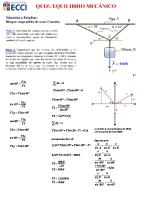
Rocket Equation Derivation Notes and Practice Problems In class we looked at deriving the rocket equation, which provides a relationship for the change in velocity of a rocket to parameters such as the exhaust velocity and mass fraction. The sketch below shows a rocket accelerating in a perfectly vertical orientation. V(t) is the velocity of the rocket relative to an inertial observer
V
y
Ve is the exit velocity of the propellant relative to the rocket and taken to be a constant
M x
The rocket has a mass M(t)
Ve
Neglecting all forces acting on the rocket and Pe=Pa, the momentum equation in the ydirection can be written as shown below: d u y dV u y u nˆ dS 0 dt V S
1
Or, written explicitly employing a moving control surface (which is fixed to the rocket): d u y dV u y u u cs nˆ dS 0 dt V S
2
The volume integral (the first term in either case) is evaluated as: d d dM dV u y dV M t V t V M dt V dt dt dt
3
To make sure that you understand this derivation completely: 1. Write down the result of the momentum flux term using the form of the ymomentum equation expressed in Equation 1. 2. Write down the result of the momentum flux term using the form of the ymomentum equation expressed in Equation 1. 3. Use the results of Part 1 and Part 2 to develop the Ideal Rocket Equation. 4. Compare the results of Equation 1 and Equation 2 to the Rocket Car example (rocket launched horizontally) developed in lecture.
1
The key to these problems is to pay strict detail to the sign convention and deal with the outward-normal on the control surface properly. Below is the solution for the momentum flux term, which is the second term of the Equations 1 and 2. Also, for simplicity, the integral of the area is Ae and the density is e, both of which are constant. Part 1: Solution using Equation 1 Using Equation 1: u u nˆ dS 0 y
S.1
S
Taking the density and area out of the integral we have: e Ae u y u nˆ 0
S.2
We have to be very careful in evaluating each of these terms, but remember that we are interested in velocities and fluxes across a surface. The surface that we are interested in is the exit plane of the rocket. This is the only place on the control volume where a velocity, mass or momentum flux is crossing a surface. Now look at each term: The first one is uy, which is the velocity of the exit propellant in the inertial frame (ground-based observer). The velocity of that exit propellant can be determined as follows in an inertial frame. o What is the velocity of the quantity that is crossing the control surface? It is Ve, but it is negative based on our sign convention (it is in the negative y direction). o Next, what is the velocity of the control volume (or the control surface)? Its velocity is V and it is positive since it is in the positive y-direction. o The sum of these is the inertial velocity of the propellant that is crossing the control surface: -Ve+V, or V-Ve. This is the velocity that an inertial observer would measure for the exit propellant. o Note: There is no dot product on this term, it is done. The next term is u nˆ , which is the velocity of the propellant crossing the control surface in the relative frame. Also note that this is the dot product of two vectors, which means that we need to pay careful attention to the direction of the normal vectors to the control surface (which always point outward). We can evaluate this term as follows: o What is the velocity of the propellant? It is –Ve, since it is in the negative y-direction. The normal vector is drawn pointing outward and it is also in the negative y-direction. o The dot product of –Ve in the direction of n is Ve.
2
o Notice that when Ve is in the direction of n (regardless of the sign convention) the result will be a positive quantity (compare to the rocket car in class). This is by convention. We define positive momentum flux as out of the control volume and negative momentum flux as into the control volume. This is by convention and is the reason that we draw the normal unit vectors outward. We can write this out completely now: e Ae u y u nˆ e Ae V Ve Ve 1 0
S.3
Simplifying, we have: eV m eVe 0 e Ae u y u nˆ e AeVVe e AeVe2 m
S.4
The momentum flux term in the y-direction (the only direction with a flux term) is: eV m eVe e Ae u y u nˆ m
S.5
Part 2: Solution using Equation 2: The quantity we are interested in evaluating can be written in the y-direction as: u u u nˆdS y
cs
S.6
S
We have to be very careful in evaluating each of these terms, but remember that we are interested in velocities and fluxes across a surface. The surface that we are interested in is the exit plane of the rocket. This is the only place on the control volume where a velocity, mass or momentum flux is crossing a surface. Now look at each term (same as above, this term never changes between the two forms): The first one is uy, which is the velocity of the exit propellant in the inertial frame (ground-based observer). The velocity of that exit propellant can be determined as follows in an inertial frame. o What is the velocity of the quantity that is crossing the control surface? It is Ve, but it is negative based on our sign convention (it is in the negative y direction. o Next, what is the velocity of the control volume (or the control surface)? Its velocity is V and it is positive since it is in the positive y-direction. o The sum of these is the inertial velocity of the propellant that is crossing the control surface: -Ve+V, or V-Ve. This is the velocity that an inertial observer would measure for the exit propellant.
3
o Note: There is no dot product on this term, it is done. Also notice that it is identical to the operations performed in Part 1. The next term is u u cs nˆ . This entire quantity is the velocity of the propellant crossing the control surface in the relative frame. Within this quantity the first u is inertial and the second is the velocity of the control surface. Lets look at it piece by piece: o The first term, u , is the same as above. It is the velocity of the propellant across the control surface as observed from an inertial frame, V-Ve o The second term is the velocity of the control surface. The control surface is moving in the positive y-direction, so ucs is equation to V. o Now we need to take this sum [(V-Ve)-V], and dot it with the normal vector. The sum is equal to –Ve, and the normal vector is in the negative ydirection. So we have Ve 1 Ve
We can write this out completely now:
e Ae u y u u cs nˆ e Ae V Ve V Ve V 1
S.7
Simplifying, we have: e Ae u y u u cs nˆ e Ae V Ve Ve 1 e AeVVe e AeVeVe
S.8
The momentum flux term in the y-direction (the only direction with a flux term) is: eV m eVe e Ae u y u u cs nˆ e AeVVe e AeVeVe m
S.9
Comparing Equations S.5 and S.9, we see that the result of using either form of the momentum equation will result in the same answer. Part 3: Application of this result to the development of the idea rocket equation These momentum flux terms can be combined with the part that I gave you in Equation 3 to derive the rocket equation. Combining these results: dM dV eV m eV e 0 V M m dt dt
S.10
We can write the term dM/dt as: dM dm e m dt dt
Substituting this into Equation S.10:
4
S.11
eV M m
dV eV m eVe 0 m dt
S.12
We can simplify and show that: M
S.13
dV eVe m dt
Employing Equation S.11 and solving for the incremental velocity change dV: dV
eVe m dM dt Ve M M
S.14
We can now integrate Equation S.14, from initial to final conditions, and making the assumption that Ve is constant. Vf
Mf
Vi
Mi
dV Ve
S.15
dM M
Integration gives: Mf Mi
V f Vi Ve ln
Mi M f
Ve ln
S.16
This is Equation 10.11 shown in Section 10.3 of the text book. Part 4: How does this result compare to the rocket car shown in lecture? First note, that this is exactly the same problem. The rocket car is traveling horizontally and we are neglecting drag and assuming Pe=Pa. The rocket shown on page 1 is traveling vertically with Pe=Pa, and we are neglecting drag as well as gravity. The difference between the rocket in vertical flight and the rocket car is the sign convention. Note that for the rocket car, the car is traveling in the negative x-direction and the propellant is being exhausted in the positive x-direction. Notice also that, as always, all the normal unit vectors to the control surface point outward. Let’s look at the derivation we did in class again, and compare it term by term to the derivation done here and see where the sign convention and normal vectors play important roles. The volume integral of the momentum equation, shown in Equation 3 is evaluated as:
5
d d dM dV u y dV M t V t V M dt V dt dt dt
3
For the Rocket Car, it is: d d dM dV u y dV M t V t V M dt V dt dt dt
3.RC
This is because the rocket car is moving in the negative x-direction and hence its velocity is in the negative x-direction. The structure of the terms is the same, the direction has changed. Now look at the momentum flux terms: For the vertically launched rocket, we showed using Equation 1, that: eV m eVe e Ae u y u nˆ m
S.5
For the rocket car, this equation would be modified to read:
e Ae u x u nˆ e Ae Ve V Ve 1 m eV m eVe
S.5 RC
It is almost the same as S.5, except the signs are flipped, because the sign convention was flipped. We can do the same thing using Equation 2, and the result that was shown for the vertically launched rocket, from Equation S.7 was: e Ae u y u u cs nˆ e Ae V Ve Ve 1 e AeVVe e AeVeVe
S.8
For the rocket car, we have:
e Ae u x u u cs nˆ e Ae Ve V Ve V V 1 e AeVVe e AeVeVe S.8 SR Notice that just the signs switched, but notice that the sign of the momentum flux term relative to the rocket or the rocket car didn’t change. This again is because of convention. Whenever there is an outward momentum flux it will yield a positive value. If we proceed to combine these terms, we can derive the rocket equation for the car. Combining terms we have:
dM dV eV m eVe 0 V M m dt dt
Again employ Equation S.11, to yield:
6
S.17
eV M m
dV eV m eVe 0 m dt
S.18
Which can be simplified to: M
dV eVe m dt
S.19
This is exactly the same result which was obtained in the vertical rocket case, shown in S.13. That means that the same rocket equation will result when Equation S.19 is integrated. But wait! If the coordinate system has switched signs, shouldn’t the resulting direction of V change in the final result of the rocket equation? The answer is no. This equation is predicting velocity in the direction you drew the velocity vectors in. For example, in the rocket car, the velocity vector of the car was drawn in the –x-direction. The result for a positive Ve will be a positive V from the equation, but you have to look at your velocity vector to determine which direction the car is going, which is always in the opposite direction of Ve. The same is true of the vertically launched rocket.
7