Hydromatic Brake New Catalog HB-1-10
Parmac L.L.C. P.O. BOX 1149, 201 East 12th COFFEYVILLE, KS 67337-0914 PHONE 620-251-5000, FAX 620-251-0225 web site : pa
Views 21 Downloads 0 File size 4MB
Recommend stories


- Author / Uploaded
- Lucas Maldonado
Citation preview
Parmac L.L.C. P.O. BOX 1149, 201 East 12th COFFEYVILLE, KS 67337-0914 PHONE 620-251-5000, FAX 620-251-0225 web site : parmacbrake.com e-mail : [email protected]
HYDROMATIC BRAKE CATALOG HB-1-10 TABLE OF CONTENTS GENERAL DESCRIPTION………………………………………………PAGE 2 APPLICATION FOR WORKOVER AND DRILLING RIGS………....PAGE 2 -3 PROCEDURE FOR SIZING DIRECT CONNECTED BRAKE………PAGE 3 -4 PROCEDURE FOR SIZING INDIRECT CONNECTED BRAKE……PAGE 4 - 5 APPLICATION FOR ANCHOR WINDLASS………………...………...PAGE 5 - 6 APPLICATION FOR GAS VAPORIZATION SYSTEM………………PAGE 6 INSTALLATION…………………………………………………………...PAGE 7 LUBRICATION…………………………………………………………….PAGE 7 FLUID SYSTEM……………………………………………………………PAGE 7- 10 SUMMARY………………………………………………………………….PAGE 11 TABLE 1, Effective Drum Diameter……………………………………….PAGE 12 TABLE 2, Drum Speed Factors…………………………………………….PAGE 13 TABLE 3, ORQ Stud Link Mooring Chain….…………………………….PAGE 14 PUMP FEED FLUID SYSTEM……………………………………….……PAGE 15 LEVEL CONTROL FLUID SYSTEM………………………….…………PAGE 16 ALTERNATE PUMP FEED SYSTEM………………………….….….…...PAGE 17 COMPARISON OF HYDROMATIC® BRAKE MODELS…….…..…….PAGE 18 TABLE 4, Hydromatic® Brakes or Hydrotarders®…..………………..….PAGE 19 BRAKE INSTALLATION DIMENSIONS………………………..……….PAGE 20 - 29 BRAKE PERFORMANCE CURVES.……………………….….…………PAGE 30 – 44 PARMAC SALES OFFICES………………………………………………..PAGE 45
GENERAL DESCRIPTION Parmac L.L.C. V-200 Hydromatic Brake
The Hydromatic Brake is a hydrodynamic device that absorbs power by converting mechanical energy into heat in the working fluid, which is normally water. Resistance is created exclusively by fluid friction and agitation of the fluid being circulated between the vaned pockets of the rotor and the facing vaned pockets of the stator. the amount of mechanical energy that can be absorbed in this manner is dependent upon the quantity and velocity of the fluid in the working chamber. The velocity of any specific quantity of fluid in the working chamber will be increased with the rotary speed of the rotor up to the maximum operating speed of the brake. Hydromatic Brakes and Hydrotarders are versatile pieces of equipment. Originally developed for use on heavy duty rotary drilling rigs, their uses have spread to other areas such as cranes, hoists, on and off highway vehicles, conveyors, engine dynamometers, anchor windlasses and winches, non-fired gas evaporation systems, and many others. Any equipment which generates surplus energy can profit from the smooth fluid action, and power absorbing efficiency of the Hydromatic Brake or Hydrotarder. The capacity curves give torque versus RPM, and horsepower versus RPM, for the various sizes of Hydromatic Brakes and Hydrotarders. The brake torque and horsepower curves are not included in this publication, and are available as a separate attachement e-mail from Parmac LL.C. APPLICATION OF THE HYDROMATIC® BRAKE OR HYDROTARDER® ON WORKOVER AND DRILLING RIGS The Hydromatic Brake has been used primarily on oil drilling rigs to retard the descent of the drill pipe into the well. The material in this catalog is oriented toward drilling rig installations, but also applies to other uses of the brake.
Due to difference in design between rigs, the correct brake size should not be determined by drilling depth or rig horsepower. the Hydromatic Brake selected must be able to retard the maximum hook load encountered by the workover or drilling rig to a predetermined safe speed. Parmac does not specify hook speeds to be used as design parameters for the rigs. It is the rig manufacturer’s or end user’s responsibility to determine the hook speeds required for safe operation of the rig. A hook speed of 200 feet per minute (FPM) has been set as a reasonable speed for drilling rigs, however higher hook speeds may be desired on workover rigs depending upon the load being lowered. Parmac does not recommend hook speeds in excess of 300 FPM.
THE HYDROMATIC BRAKE IS A SPEED RETARDING DEVICE ONLY AND CANNOT COMPLETELY STOP THE LOAD BEING CONTROLLED. THE HYDROMATIC BRAKE IS USED TO CONTROL THE DESCENT OF THE HOOK LOAD TO A SPEED THE DRAWWORKS FRICTION BRAKE CAN STOP SAFELY. Since numerous sizes of workover and drilling rigs are manufactured, the Hydromatic Brake is made in various sizes and must be matched to the intended rig application in order for the brake to perform satisfactorily.
It is common practice on oil drilling rigs to trip one stand of drill pipe every minute. Using a 90 ft. stand, a speed of
2
200 FPM will allow 27 seconds for lowering the stand and 33 seconds for making up the next stand of pipe.
are terms used in calculations for selecting Hydromatic Brakes.
The hook load descending at a specific speed develops a particular torque and RPM, or horsepower, to be absorbed at the hoisting drum. Since the absorption ability of the Hydromatic Brake is speed dependent it must be sized to develop the same horsepower as generated by the descending hook load.
BRAKE SIZING TERMS
There are two different installation types: DIRECT CONNECTED and INDIRECT CONNECTED. The Direct Connected Hydromatic is directly coupled to the hoisting drum and therefore rotates at the same RPM as the drum. The Indirect Connected Hydromatic is coupled to the drum through a mechanical drive that allows the brake to operate at a greater rotational speed than the drum. Parmac does not recommend speed increase ratios (R) greater than 5. Brake Models 262 and smaller are designed to be indirect connected where Brake Models 341 and larger are designed to be direct connected ONLY.
D = Actual Drum Diameter (inches) d = Wire Line Diameter (inches) Db = Bare Drum Diameter (inches) H = Hook Load (lbs.) L = Number of Lines Nb = Brake RPM Nd = Drum RPM Nmax = Maximum Brake RPM R = Speed Increase Ratio S = Hook Speed (ft./min.) (FPM) Smax = Maximum Hook Speed encountered by the Rig (FPM) Tb = Brake Torque (lbs.-ft.) Td = Drum Torque (lbs.-ft.) π = 3.14 BRAKE SIZING FORMULA
Most workover and drilling rigs contain bare drums with grooved sleeves to properly wrap the wire line. Standard grooved lagging will increase the actual drum diameter 1 inch. When the traveling blocks are completely hoisted, the hoisting drum may contain 4 or 5 layers of wire line. With the blocks completely lowered one layer of wire line may remain on the drum. It has been Parmac’s standard practice to base all calculations on the actual operating drum diameter. TABLE 4 gives the actual drum diameter, for different bare drum diameters, and wire line sizes, for the 1st through the 4th layer of line. The Hydromatic Brake Calculator (slide rule) uses the 3rd layer of nominal wire line for all calculations. The horsepower curve and torque curve published for each brake describes the power absorption when the brake is full or supplied to maximum capacity with water or fluid, this is full brake operation. Additional brake absorption cannot be obtained by any other means such as restricting the outlet fluid flow or increasing the fluid pressure. Power absorption less than the maximum can be obtained at any RPM by decreasing the fluid flow through the brake or the amount of fluid contained in the brake. This is partial brake operation. The brake will not operate at a constant or steady speed from zero load to maximum load. To insure steady or satisfactory brake control the minimum hook load should not be less than 20% of the full brake maximum hook load.
Td = (H) (D) (L) (24)
H = (Td) (L) (24) D
Nd = (S) (L) (12) (π) (D)
S = (Nd) (π) (D) (L) (12)
HP =
(H) (S) 33000
Tb =
HP =
(Td) (Nd) 5252
=
Td (Idirect R Connected)
(Tb) (Nb) 5252
Tb = Td ( Direct Connected ) Nb = (Nd) (R) (Indirect Connected) PROCEDURE FOR SIZING A DIRECT CONNECTED BRAKE 1.
Obtain the following information: a) H- Maximum Hook Load (lbs.) b) L- Number of Lines c) d- Wire Line Diameter (inches) d) Db- Bare Drum Diameter (inches) e) S- Desire Hook Speed at Maximum Hook Load (FPM) f) Smax- Maximum Hook Speed encountered by Rig (FPM)
In calculating brake performance the mechanical efficiencies of the drawworks, wire line, and sheaves should not be used since the efficiencies are based upon static conditions for hoisting and not upon dynamic conditions for braking. The Hydromatic Brake can be sized to the rig by using either the Hydromatic Brake Calculator, or by performing the necessary calculations. The following
3
2.
Determine the Drum Diameter (D) in inches at the third layer from TABLE 1.
3.
Calculate the Drum Torque (Td) in lbs.-ft. from this formula: Td = (H) (D) (L) (24)
4.
Calculate the Drum RPM (Nd) from this formula:
7.
Nd = (S) (L) (12) (π) (D) 5.
The brake chosen must develop the calculated torque (Td) at or below the calculated (Nd). Once a brake satisfying this requirement is chosen, follow the brake torque curve to Td and note the brake operating RPM (Nb).
6.
Calculate the actual Hook Speed at Maximum Hook Load from this equation:
Nb = (300) (10) (12) (π) (36.58)
Check to see that the Brake RPM (Nb) will not exceed the Maximum Brake RPM (Nmax) from TABLE 4. Page 11 at the Maximum Hook Speed (Smax) encountered by the rig from the following formula:
f)
If Nb is greater than the Maximum Brake RPM for the chosen brake, then another brake must be selected.
Assume drilling to 20,000 ft. depth with 4 ½ ” drill pipe @ 16.6 lbs./ft. 50,000 lbs. of drill collars, 10 lines, 30 inch bare drum, and 1 ¼” wire line. The desired Hook Speed at Maximum Hook Load is 200 FPM and the Maximum Hook Speed encountered by the rig is 300 FPM. (a) H= (20,000 ft.) (16.6 lbs./ft.) + 50,000 lbs. = 382,000 lbs. (b) L = 10 (c) d = 1 ¼ inches (d) Db = 30 inches (e) S = 200 FPM (f) Smax = 300 FPM
Determine the Drum Diameter (D) in inches at the third layer from TABLE 1.
3.
Calculate the Drum Torque (Td) in lab.-ft. from the following formula: Td = (H) (D) (L) (24)
4.
5.
Calculate the Drum RPM (Nd) from the following formula: Nd = (S) (L) (12) (π) (D) Calculate the Horsepower (HP) to be absorbed by the brake using either of the following equations: HP =
(Td) (Nd) 5252
OR
2.
D = 36.58 inches (3rd layer) from TABLE 1.
3.
Td = (382,000) (36.58) = 58,223 lbs.-ft. (10) (24) Nd = (200) (10) (12) = 209 RPM (π) (36.58) Thus, a brake that will develop 58,223 lbs.-ft. of torque at 209 RPM or less is required. The torque curve of the 481 Hydromatic Brake, indicates that 58,223 lbs.-ft. torque will be developed at 160 RPM.
6.
H- Maximum Hook Load (lbs.) L- Number of Lines d- Wire Line Diameter (inches) Db- Bare Drum Diameter (inches) S- Desired Hook Speed at Maximum Hook Load (FPM) Smax- Maximum Hook Speed encountered by Rig (FPM)
2.
EXAMPLE: Direct Connected Brake
5.
Obtain the following information: a) b) c) d) e)
Nb = ( Smax) (L) (12) (π) (D)
4.
313 RPM
PROCEDURE FOR SIZING A INDIRECT CONNECTED BRAKE 1.
1.
=
This RPM is less than the maximum of 450 RPM for a 481 Hydromatic Brake as listed in TABLE 4. Therefore, a 481 Hydromatic brake will perform satisfactorily in this application.
S= (Nb) (π) (D) (L) (12) 7.
At the Maximum Hook Speed encountered by the rig
HP=
6.
(H) (S) 33,000 From the Horsepower Curves, listed in the catalog, select a brake that will develop the required horsepower calculated in the step 5.
7.
From the Horsepower Curve of the selected brake determine the RPM (Nb) at which the brake will develop the required horsepower.
8.
Determine the Speed Increase Ratio -R- from the following equation:
Calculate the actual Hook Speed at Maximum Hook Load if using the 481 Hydromatic Brake.
R=
S = (160) (π) (36.58) = 153 FPM (10) (12) The 481 Hydromatic Brake will perform better than the anticipated 200 RPM with the maximum hook load.
9.
4
Nb Nd If R is greater than 5, select a brake that develops greater horsepower until a brake is found for which -R- is less than 5.
10. Check to see that the Maximum Hook Speed, (Smax) will not be exceeded and cause the brake to over speed.
10. Check to see that the Brake RPM (Nb) will not exceed the maximum Brake RPM (Nmax), TABLE 4. at the Maximum Hook Speed (Smax) encountered by using the following formula:
Nb = (2.46) (300) (12) (π) (24.02)
Nb = (R) (Smax) (L) (12) (π) (D)
=
939 RPM
The Maximum Brake RPM or, Nmax, of the 202 Hydromatic Brake is listed as 1550 RPM in TABLE 4. Since 939 RPM is less than 1550 RPM, the 202 Hydromatic Brake will retard the load to 200 RPM and will not over speed at a hook speed of 300 FPM.
If Nb is greater than the Maximum Brake RPM, then a larger capacity brake must be selected. EXAMPLE: Indirect Connected Brake Assume 200,000 lbs. maximum hook load, 8 lines, 18 inch diameter bare drum, and 1 1/8” diameter wire line. The desired Hook Speed at Maximum Hook Load is 200 FPM and the Maximum Hook Speed encountered by the rig is 300 RPM. 1.
APPLICATION OF THE HYDROMATIC® BRAKE OR HYDROTARDER® TO AN ANCHOR WINDLASS The Hydromatic Brake selected must be able to retard the maximum chain tension or wire line tension applied to the wildcat or drum, to a desired or predetermined speed.
a) H = 200,000 lbs. b) L = 8 c) d = 1 1/8” d) Db = 18 inches e) S = 200 FPM f) Smax = 300 FPM
Chain or wire line speeds of 300 FPM (feet per minute) or greater have been used in the past but 200 FPM has been determined to be a more reasonable and safer operating speed during dynamic pay out of the chain.
2.
D = 24.02 inches (3rd layer) from TABLE 1.
The horsepower absorption, required by the Hydromatic Brake, can be determined by substituting the chain or wire line tension for Hook Load (H), in pounds (lbs), and the line speed for Hook Speed (S), in ft/min (FPM), in the horsepower formula previously mentioned in the drilling rig application.
3.
Td = (200,000) (24.020 (8) (24)
=
25,021 lbs.-ft.
4.
Nd =
(200) (8) (12) (π) (24.02)
=
254 RPM
5.
HP =
(25,021) (254) 5252
=
1210 HP
HP =
(200,000) (200) 33,000
=
1210 HP
HP = (H) (S) 33,000 TABLE 3 lists the wildcat data for different sizes of ORQ Stud-Link chain commonly used in the mooring of offshore rigs, and is available from Parmac upon request. The wire line drum will contain a considerable length of cable and may have up to 12 layers of line. The diameter of the drum, at the largest layer, should be used to determine the brake retarding speed, since as line is payed out the drum diameter becomes smaller, resulting in slower pay out speeds.
6.
From TABLE 4., it can be seen that a 122 Hydromatic Brake will develop a maximum of 1600 HP.
7.
From the Horsepower Curve, for the 122, the 122 Hydromatic Brake will develop 1210 HP at 1420 RPM.
8.
Calculate Speed Increase Ratio. R=
9.
1420 254
The required wildcat RPM that corresponds to the desired chain speed can be determined by dividing the chain speed (FPM), by the length of chain for one revolution, (Ft/Rev) of the wildcat. Wildcat RPM =
Chain Speed (FPM) Chain Length (Ft/Revolution)
From the brake Horsepower Curves select a brake that will develop the required horsepower previously determined.
= 5.59
The Speed Increase Ratio (R) required between the wildcat and the Hydromatic Brake is determined by:
Since R is greater than 5 the larger 202 Hydromatic Brake is chosen. The 202 Horsepower Curve, indicates that the 1210 HP at 626 RPM is developed. Therefore, R = (626/254) = 2.46, which is less than 5.
R =
5
Nb Wildcat RPM
EXAMPLE: Windlass Application Assume 2 ½ inch chain with a maximum tension of 200,000 lbs. and the desired chain speed is 200 FPM.
APPLICATION OF THE HYDROMATIC® BRAKE FOR GAS VAPORIZATION SYSTEMS
From the Horsepower formula. HP = (200,000 lbs.) (200 FPM) = 1212 HP 33,000 From TABLE 3 for 2 ½ inch chain: One revolution = 8.33 ft. or feet per revolution = 3.33(Chain Size) = 3.33(2.5) Wildcat RPM = 200 ft/min 8.33 ft/rev
Nitrogen vaporization units are used to pump the vaporized liquid nitrogen into an oil well using a nitrogen triplex pump hydraulically driven by the diesel engine. to maximize the heat output, of the engine, and to obtain the greatest amount of vaporization, the Hydromatic Brake is connected to the engine and loads the engine creating more engine waste heat while converting the Brake heat directly into the engine coolant.
= 24 RPM
From the Horsepower Curves the V-80 Brake will develop 1212 horsepower at 480 RPM. The required speed increase ratio between the wildcat and V-80 Brake is: R =
Flameless, liquid gas, vaporization units have been designed and manufactured that use the heat generated by a prime mover instead of the heat from a heat exchanger using a combustible fuel. The prime mover is normally a diesel engine.
The nitrogen pump, and the engine coolant pump are driven by hydraulic motors that are powered by two separate hydraulic pumps mounted on an engine pump drive.
Nb = 480 RPM = 20 or 20:1 Ratio Wildcat RPM 24 RPM
If the mooring system is a combination system consisting of chain and wire line, the wire line drum must be analyzed also.
To eliminate manufacturing a separate mounting for the Hydromatic Brake, and to reduce cost, several models of Hydromatic Brakes are available that mount directly to the engine pump drive. Normally, a triple pump drive is used to mount both hydraulic pumps and the Hydromatic Brake.
When all of the chain has been payed out, the wire line is then connected to the chain and the wire line payed out. When analyzing the wire line drum, the maximum chain tension will be the initial wire line tension to be used with the largest drum diameter or the drum diameter corresponding to a full drum of wire line.
The brakes are provided with involute splined shafts to mate directly with the pump drive output gear, and have standard SAE four bolt, hydraulic pump mounting flanges.
Due to the drum diameter being much larger than the diameter of the wildcat, the windlass will probably have less gear ratio for the wildcat, than the gear ratio to the drum. The drum and wildcat must be analyzed for their respective ratios to obtain payout speeds for both the chain and wire line.
The brakes can be mounted using a remote mounting, instead of the pump drive, and line driven from the engine pump drive using a drive shaft with flexible joints. The brakes have been designed to operate at a maximum continuous speed of 2300 RPM, provided special lubricating and cooling circuits are connected to the brake.
The chain or wire line payout speed can be increased by regulating a control valve in the brake inlet line which allows the operator to select the maximum line speed.
The nitrogen vaporization brake models must be line driven and are incapable of supporting a shaft side load from a gear or chain sprocket mounted on the brake shaft.
The Brake speed could exceed the rated RPM of the Brake when the wire line is on the smallest diameter or layer of the drum and the operator has reduced the Brake retarding, to maintain the same line speed. Once the speed ratio (R) has been determined the maximum RPM of the brake, at maximum line speed, with the smallest drum diameter, should be checked to determine that the Brake will not be over speeded.
The specific models of brakes, for the gas or nitrogen vaporization application, are the 111-300 and 112-500 brake models, and are not recommended for other Hydromatic Brake applications such as drilling or workover rig applications.
Using the maximum line speed to be allowed, a drum RPM must be determined and multiplied by the speed ratio to obtain the maximum Brake RPM. The maximum Brake RPM should not exceed the rated RPM of the Brake, listed in TABLE 4.
Other models of Hydromatic Brakes are available for gas vaporization applications. Consult Parmac’s Engineering Dept. for availability and recommendations.
6
may be INDIRECT CONNECTED. Brake sizes 341 and larger do not have bearings and shafts capable of side loads and must be DIRECT CONNECTED to the energy machine and subjected to only torque loadings.
INSTALLATION
When properly installed, the Hydromatic Brake becomes part of a mechanical system. Certain precautions should be observed in the installation of the Hydromatic Brake and the design of the supporting and connecting equipment THE HYDROMATIC BRAKE WORKS AS A RETARDING DEVICE ONLY, AND WILL REDUCE INPUT SPEED, BUT WILL NOT BRING THE INPUT SPEED TO A COMPLETE STOP. OTHER MEANS OF BRINGING THE INPUT SPEED TO A COMPLETE STOP MUST BE PROVIDED IN THE DESIGN OF THE MECHANICAL SYSTEM TO WHICH THE HYDROMATIC BRAKE IS CONNECTED. Lugs or bosses with tapped holes are provided on each side of the Hydromatic Brake for mounting. Each Hydromatic Brake contains a machined pilot for positioning the brake in the mounting brackets for correct alignment of the brake. The machined pilot must be utilized, when the brake is subjected to side loads, to prevent shearing of the mounting bolts. Mounting brackets and supports of sufficient strength and stiffness must be provided by the designer of the supporting equipment. In all cases, the Hydromatic Brake must be supported on each side so as not to create a twisting moment in the brake housing, caused from overhung shaft loads.
The Direct Connected shaft of the Hydromatic Brake is subjected to torque loading. The Indirect Connected Hydromatic Brake shaft is subject to both torque and bending loads which are induced by the connecting chain or gear drive. The customer must furnish the manufacturer with loading information in order that shaft stresses and bearing life may be calculated. The loading information should include the maximum amount of torque to be absorbed, the maximum service operating speed of the brake, the pinion pitch diameter of the chain or gear pinion mounted on the brake shaft, and the distance from the centerline of the brake to the centerline of the chain or gear pinion plus the dead weight of all equipment mounted on the brake shaft. On all installations, care must be taken that the brake is mounted in such a manner that a drain connection is provided to insure complete draining of the brake. LUBRICATION Lubrication instructions are included on the name plate. Lubrication fittings are provided on each side of the brake for the bearings and seals. When the brake is in use the seals should be lubricated before and after each round trip with several strokes of the grease compressor. The bearings should also be lubricated before and after each round trip with two or three strokes of the grease compressor. On rigs operating at great depths, the lubrication should be increased to twice a trip to increase the life of the seals and bearings. Care should be taken to be sure the relief fittings and weep holes are clean.
The Hydromatic Brake may be connected to the output shaft of the energy machine through a flexible coupling, through a disengaging type clutch, or an overrunning clutch. This type of installation is termed a Direct Connected brake. Connecting clutches must NOT be engaged or disengaged when the Hydromatic Brake is in motion to avoid shock loadings.
Use No. 2 water resistant (calcium base) grease for both the seals and bearings. Other specific lubrication instructions are included in the Repair and Maintenance Instructions included with each brake assembly.
Alignment between the Hydromatic Brake shaft and the output shaft of the connecting energy machine must be maintained at all times. On some installations, a chain or gear speed increasing drive is utilized between the energy machine and the Hydromatic Brake shaft. this is termed an Indirect Connected application.
FLUID SYSTEM The Hydromatic Brake must contain fluid in the working chamber to function as a brake and absorb mechanical energy.
In all cases the size, capacity, and method of operation of all couplings, clutches, chain drives or gear drives connected to the Hydromatic Brake is the responsibility of the manufacturer of the mechanical system to which the Hydromatic Brake is connected.
An adequate supply of the fluid must be supplied to the Hydromatic Brake by a supporting fluid system. The Hydromatic Brake is not self charging, and a positive head must be maintained at the brake inlet during operation.
Brake sizes from 121 though 262 contain bearings and shafts capable of side loads from chains or gears and
7
ALLOWABLE BRAKE OUTLET TEMPERATURE MUST NEVER EXCEED 180°F.
Torque resistance of the Hydromatic Brake cannot be increased by raising the internal fluid pressure, either by increasing pump supply pressure or back pressuring the brake by installing valves or restrictions in the brake outlet line.
Outlet water temperatures higher than 180°F could allow steam to form in the working chambers of the brake. When this condition exists, the fluid is forced from the brake, by the steam pressure, with a consequent loss of retarding torque and the inability of the brake to retard the load.
Excessive internal pressure will shorten the life of the shaft seal. The recommended maximum inlet pressures for all size brakes are shown in TABLE 4. The type of fluid control system used with the Hydromatic brake is dependent upon the particular brake application. THE FLUID SYSTEM MUST BE DESIGNED SO THAT THE HYDROMATIC BRAKE CANNOT BE OPERATED ABOVE THE MAXIMUM ROTATIONAL SPEEDS LISTED IN TABLE 1. EXCEEDING THE LISTED SPEED OF THE BRAKE, RESULTLS IN DANGEROUS OVER SPEED OF THE BRAKE ROTOR, THAT MAY CAUSE THE ROTOR TO SEPARATE, RESULTING IN CATASTROPHIC FAILURE OF THE BRAKE AND CAUSING SERIOUS BODILY INJURY OR DEATH TO NEARBY PERSONNEL. THE OVER SPEED CONDITION CAN RESULT FROM REDUCING THE FLUID OUTFLOW FROM THE BRAKE, DUE TO VALVES OR RESTRICTIONS IN THE OUTLET LINE, OR BY FAILURE TO PROVIDE ADEQUATE FLUID INFLOW TO THE BRAKE. The fluid flow through the Hydromatic brake must meet the following two requirements:
DO NOT INSTALL VALVES OR FLOW RESTRICTIONS IN THE OUTLET LINE, THEY WILL NOT PROVIDE BRAKE CONTROL, AND WILL REDUCE THE FLUID OUTFLOW, AND BACK PRESSURE THE BRAKE.
Since the brake is a component of other equipment, and many variations exist in the installation of the brake, Parmac does not design or provide a fluid or brake control systems for the brake. It is the equipment designer’s responsibility to design and provide a safe and operable brake control fluid system. The following discussion of different types of fluid systems is provided to help the designer in selecting and designing the correct system. Regardless of the type of system used, the brake control designer and manufacturer must be aware of possible over speeding of the bake, and provide in the BRAKE OPERATOR’S MANUAL, the safe operating speeds of the equipment that will prevent over speeding of the brake. The manual should also warn or alert the operator, or end user, of the dangers and consequence of over speeding the brake.
(1) The torque rating curves of the Hydromatic Brake are based on a condition where the brake is completely full of fluid during the operating cycle. THE RETARDING TORQUE IS BASED UPON THE AMOUNT OF FLUID CONTAINED IN THE ROTOR AND STATOR POCKET SECTIONS OF THE BRAKE DURING OPERATION.
Since other personnel, other than the brake operator, are involved in the operation of the equipment and connected brake, the equipment operator should inform all personnel of the dangers that can occur from unsafe operation of the brake.
In other words, the brake must contain a proportionate amount of fluid in order to retard the coupled load. As this is a balance of the inlet flow, TO the brake, and the outlet flow, FROM the brake, the system must be capable of providing adequate flow to obtain full brake performance. FLOW REDUCING DEVICES SUCH AS REDUCERS, STRAINERS, EXCESS PIPE CONNECTIONS, SHOULD NOT BE INSTALLED IN THE INLET LINE, SINCE THE FLUID INFLOW MAY BE INSUFFICIENT AND RESULT IN BRAKE OVER SPEEDING. (2) The heat generated, in the brake, due to the retarding of the coupled energy load, is transferred directly to the fluid being circulated through the brake; therefore A SUFFICIENT FLOW OF COOL FLUID MUST BE PROVIDED THROUGH THE BRAKE TO PREVENT A HEAT BUILDUP IN THE BRAKE. WHEN WATER IS USED AS THE BRAKING MEDIUM, THE MAXIMUM
8
An inlet valve in the brake inlet line, or a fluid level system is required for brake control and to vary the brake retarding for loads less than the maximum. There are three basic fluid systems that may be used in conjunction with the Hydromatic Brake. The Pump Feed System, shown in the catalog, illustrates whereby the fluid is supplied to the brake by a centrifugal pump which pumps fluid from a supply tank, through an inlet valve to the working chambers of the brake. The Gravity Feed, or without the pump, may be used provided the supply tank is elevated above the brake to maintain a positive head or pressure on the brake inlet. The Gravity Feed system is not recommended unless the supply tank is next to the brake, to reduce inlet line losses,
The amount of fluid to be circulated through the brake to handle a specific horsepower load is calculate by the equation:
and a head pressure of 10 to 15 feet can be obtained from the elevated tank. The Gravity Feed or Pump Feed System is recommended for indirect connected brakes of sizes 121 through 262, and have a manual or remote operated inlet valve for brake control.
GPM =
The Level Control System, illustrates a type of fluid system that should only be used on brakes larger than the 262 brake. This system may be used on sizes 341 through V-295. Use of the level control system on smaller brakes will not provide adequate brake control.
(HP) (5.08) (∆T) (Sh)
Where: HP = Horsepower generated by the descending load ∆T = Temperature difference between inlet and outlet water of the brake in degrees Fahrenheit Sh = Specific Heat of the fluid, which is 1 for pure water
This fluid supply system utilizes a fluid level control tank which allows the operator to choose a fluid level proportionate to the torque retardation required. The type of level control tank shown is typical.
The horsepower generated by a falling load is dependent upon the weight of the load and the retarding speed of the brake. The horsepower equation is:
Different types are available from suppliers, or may be manufactured by the customer. Caution should be taken to maintain the minimum sizes of level control tanks, shown in the table, for the size of brake used.
HP = (L) (S) 33,000 Where: L = Load in pounds S = Lowering speed of load in feet per minute.
The fluid level in the level control tank must be adjustable by using level control valves, as shown, or other means of varying the level such as a level control valve. The level control tank must be vented to avoid pressurizing the brake. The level control tank must be supplied fluid, normally by a pump, from the main supply tank or heat sink, to remove the heat generated from a drop of the drill pipe. Since the brake is normally used intermittently, the pump flowrate should be capable of removing the heat of a drop, during the time required to make up and drop a stand pipe. The minimum water level, in the tank, should never be below the brake supply line connection, in the tank, to avoid air entering the supply line of the brake.
EXAMPLE: Using the two formulas L = Hook Load = 700,000 lbs S = Lowering speed of brake = 100 ft per minute HP = (L) (S) = (700,000) (100) = 2121 HP 33,000 33,000 Assuming a ∆T = Temperature Difference = 80°F Braking medium is water and Sh = 1.0 Flow of fluid required in gallons per minute GPM = (2121) (5.08) (80) (1.0)
The brake outlet line must discharge directly into the level tank to maintain the same water level, in the tank, when the brake is rotating. The discharge line from the level tank to the supply tank must be of sufficient size to prevent the pump from increasing the level in the tank, during idle periods of the brake.
=
135 GPM
The above calculations determine the required pump flowrate to maintain a certain temperature difference across the brake when being pump fed. Since the outlet water temperature is limited to 180°F, the supply tank, in the above example would be 100°F to provide a 80°F temperature difference.
A fluid control system, for size brakes 341 through V-295, with a pump, is a direct pump feed system which has some disadvantages compared to the level control system. The level control system maintains the same water level during idle periods, of the brake, which provides a constant drop speed, throughout the drop. The pump feed system will allow the brake to fill with water during the idle period and slow drop speeds will result at the start of the drop. To prevent the brake from filling with water, during idle periods, the pump feed system must be designed with the feature to prevent the brake from filling with water when idle.
All of the Hydromatic Brakes are designed for the outlet water temperature to be 180°F or less provided the brake can receive adequate flowrate from the pump or supply tank. When tripping drill pipe into a well, the heat generated by the brake is accumulative in the supply tank or heat sink. To replace the supply tank with a water to air heat exchanger is normally not feasible, due to the required size of the heat exchanger. the supply tank volume can
9
maximum pressures listed in TABLE 1. The pipe sizes, of the inlet and outlet pipes, shown on the typical fluid systems are minimum sizes. For proper flow, to and from the brake, the minimum pipe sizes must be maintained.
be reduced by using a heat exchanger in conjunction with the supply tank. On most oil drilling rigs, the existing volume of drill water is a sufficient heat sink for the Hydromatic Brake. On workover rigs, where the volume of water is limited, the required volume can be determined from the following:
On all Hydromatic Brakes, the water must enter the bottom of the brake, and exit the top of the brake, to prevent an air lock in the brake. Each brake is shipped, from Parmac, with plastic thread protectors installed in the brake inlet connections and outlet connection. The correct connections must be used for satisfactory brake performance. The correct connections are noted in this catalog, on the Brake Assembly Drawing and in the brake Repair and Maintenance Instructions.
DEFINITIONS: D = Well depth, feet L = length of stand, feet N = Number of stands X = Initial block weight with drill collars, pounds Y = Weight of one drill pipe stand, pounds T1 = Ambient temperature, of tank, degrees Fahrenheit T2 = Final water temperature, of tank, degrees Fahrenheit W = Total work for one trip, ft-lbf Q = Total heat generated for one trip, BTU’s G = Volume of water required, gallons
The Hydromatic Brake is designed for use with fresh water as the braking medium. In inclement weather conditions an anti-freeze solution, such as ethylene glycol, can be used provided the solution is not over 60% anti-freeze. All brakes are provided with a drain connection, that can also be used to drain the brake, when not in use.
Total Work for One Trip = LNX + LYN( N+1) = ft.-lbf 2
The fresh water used in the brake, for maximum operating life, should have a PH of 8.5 to 10, free of foreign matter, and the alkaline content be less than 40 parts per million.
Total Heat Generated = Q = Total Work = W = BTU 778 778 Gallons of Water Required =
Parmac manufactures brake models in a sea water version, for use of sea water, as the braking medium. Parmac does not warrant or recommend using sea water in a standard Hydromatic Brake, since the standard brake does not contain corrosion resisting materials, that is required when sea water is used as the braking medium.
Q = G = gallons 8.34( T2-T1)
EXAMPLE: X = 15,000 lbs block weight + 30,000 lbs drill collars L = 90 feet stand length D = 12,000 feet well depth Y = 1494 lbs = 16.6 lbs/ft (90 ft) for 4 ½” pipe T1 = 80°F initial water temperature T2 = 140°F (will be inlet temperature on last drop) N =
12,000 90
= 133.3 use 134 stands
Thus: W = 90(134)(45,000) + 90(1494)(134)(135) 2 W = 542,700,000 + 1,216,190,700 = 1,758,890,700 ft-lbf Q = 1,758,890,700 = 2,260,785 BTU 778 G =
2,260,785 8.34( 140-80)
= 4,518 gallons required
The inlet valve, or valve control should be located at the operator’s or driller’s console for accessibility, and the valve located as near the brake as possible. On all pressure fed systems, a pressure relief valve should be provided to limit the brake inlet pressure to the
10
SUMMARY CONSIDERATIONS in the DESIGN, MANUFACTURE and OPERATION of the LFUID SUPPLY SYSTEM and EQUIPMENT to be USED IN CONJUNCTION with a HYDROMATIC BRAKE. 1.
THE FUNCTION OF A FLUID SUPPLY AND CIRCULATING SYSTEM IS TO SUPPLY A SUFFICIENT VOLUME OF CLEAN, COOL FLUID TO THE HYDROMATIC BRAKE.
2.
A SUFFICIENT FLOW OF COOL FLUID MUST BE PROVIDED THROUGH THE BRAKE TO PREVENT A HEAT BUILDUP IN THE BRAKE.
3.
THE RETARDING TORQUE IS BASED ON THE AMOUNT OF FLUID RETAINED IN THE ROTOR AND STATOR POCKET SECTIONS OF THE BRAKE DURING OPERATION. PARMAC L.L.C. WILL ONLY BE RESPONSIBLE FOR THE TORQUE RETARDING CAPACITY OF THE HYDROMATIC BRAKE AS RATED ON THE TORQUE AND SPEED CURVES, WHEN FLUID IS FURNISHED TO THE BRAKE IN SUFFICIENT QUANTITY AND AT THE PROPER TEMPERATURE.
4.
WARNING: WITHOUT FLUID IN THE HYDROMATIC BRAKE, THERE IS NO RETARDING ACTION THE COUPLED ENERGY LOAD.
5.
IT SHALL BE THE FLUID SYSTEM DESIGNER’S RESPONSIBILITY TO DETERMINE, DESIGN, AND INSTALL AUDIBLE OR VISUAL OPERATOR WARNING DEVICES TO WARN OF LOSS OF FLUID FLOW OR FLUD PRESSURE TO THE HYDROMATIC BRAKE.
6.
WHEN WATER IS USED AS A BRAKING MEDIUM THE MAXIMUM ALLOWABLE BRAKE OUTLET WATER TEMPERATURE MUST NEVER EXCEED 180°F.
7.
IT SHALL BE THE RESPONSIBILITY OF THE FLUID SYSTEM DESIGNER TO DETERMINE THE NEED, DESIGN, AND INSTALL OUTLET WATER TEMPERATURE SENSING AND INDICATING DEVICES, AUDIBLE OR VISUAL, TO WARN THE OPERATOR OF TEMPERATURES GREATER THAN 180°F.
8.
FOR THE MOST SATISFACTORY CONTROL OF THE HYDROMATIC BRAKE, THE INLET CONTROL VALVE SHOULD BE PLACED AS NEAR THE BRAKE INLET AS POSSIBLE.
9.
ON ALL PRESSURE FED FLUID SYSTEMS, A PRESSURE RELIEF VALVE MUST BE PROVIDED IN THE BRAKE INLET SUPPLY LINE TO PREVENT INTERNAL PRESSURES GREATER THAN THE MAXIMUM SHOWN IN TABLE 1.
12. WARNING: AT NO TIME, SHOULD THE LOAD BE ALLOWED TO FREE FALL AND BE RETARDED BY ENGAGING THE BRAKE COUPLING DEVICE OR SUPPLYING FLUD TO THE HYDROMTIC BRAKE. PARMAC DISCLAIMS ANY RESPONSIBILITY OR WARRANTY ON THE HYDROMATIC BRAKE UNDER THESE OPERATING CONDITONS. THIS TYPE OF OPERATION IS UNSAFE. IT CAN RESULT IN OVER SPEEDING, AND CAUSES RAPID WEAR AND DETERIORATION OF THE HYDROMATIC BRAKE. 13. IT SHALL BE THE RESPONSIBILITY OF THE MANUFACTURER OF THE EQUIPMENT, UTILIZING A HYDROMATIC BRAKE, TO ADVISE THE OPERATIOR OR END USER AS TO THE MAXIMUM LOAD CAPACITY, THE MAXIMUM LOWERING SPEEDS, AND THE SAFE AND CORRECT OPERATIONG PROCEDURES OF THE EQUIPMENT AND THE HYDROMATIC BRAKE. 14. THE HYDROMATIC BRAKE, SOLD BY PARMAC L.L.C., IS ONLY A COMPONENT PART OF MECHANICAL EQUIPMENT, AND THE FLUID SUPPLY AND CONTROL SYSTEM DESIGN, FABRICATION, AND ALL COMPONENT PARTS USED IN THE SYSTEM IS THE RESPONSIBILITY OF THE MANUFACTURER OF THE MECHANICAL EQUIPMENT TO WHICH THE HYDROMATIC BRAKE IS CONNECTED. 15. IN ALL CASES, THE SIZE, CAPACITY, AND OPERATION OF ALL COUPLINGS, BRAKES, CLUTCHES, CHAIN DRIVES, AND GEAR DRIVES, CONNECTED TO THE HYDROMATIC BRAKE IS THE RESPONSIBILITY OF THE DESIGNER AND MANUFACTURER OF THE EQUIPMENT TO WHICH THE HYDROMATIC BRAKE IS CONNECTED. 16. THE OPERATOR AND/OR END USER OF THE HYDROMATIC BRAKE, SHALL BE RESPONSIBLE FOR THE PROPER LUBRICATION OF THE HYDROMATIC BRAKE IN ACCORDANCE WITH THE INSTRUCTIONS, PROVIDED IN THIS MANUAL, ON THE BRAKE NAME PLATE, OR REPAIR AND MAINTENANCE MANUAL PROVIDED WITH EACH BRAKE. 17. IT SHALL BE THE RESPONSIBILITY PG THE OPERATOR, AND/OR END USER TO MAINTAIN AND SAFELY OPERATE THE EQUIPMENT AT ALL TIMES. 18. PARMAC L.L.C. WILL ASSUME NO RESPONSIBILIITY FOR THE DESIGN, MANUFACTURE, MAINTENANCE, OR OPERATION OF ANY MECHANICAL EQUIPMENT CONNECTED TO THE HYDROMATIC BRAKE. 19. PARMAC L.L.C. WILL NOT BE RESPONSIBLE FOR THE DESIGN, OR PERFORMANCE OF REPLACEMENT PARTS FOR THE HYDROMATIC BRAKE NOT SOLELY MANUFACTURED BY PARMAC.
10. AT NO TIME SHOULD THE ROTATIONAL SPEEDS INDICATED IN TABLE 1, BE EXCEEDED. 11. IT SHALL BE THE RESPONSIBILITY OF THE BRAKE SYSTEM DESIGNER TO DETERMINE THE REQUIREMENT AND DESIGN AND INSTALL BRAKE SPEED SENSING DEVICES TO INDICATE, WARN OR PREVENT BRAKE OVER SPEEDING, AND ROTTIONAL SPEEDS GREATER THAN THOSE LISTED IN TABLE 1.
11
20. PARMAC DOES NOT WARRANT THE USE OF FLUID MEDIUMS OTHER THAN FRESH WATER, ESPECIALLY SEA WATER, IN HYDROMATIC BRAKES CONSTRUCTED FOR FRESH WATER USE ONLY. 21. ALL THE CONDITIONS OF RESPONSIBILITY, ARE CONTAINED IN PARMAC’S STANDARD TERMS AND CONDITIONS OF SALE.
TABLE 1 EFFECTIVE DRUM DIAMETER - HYDROMATIC® BRAKES Bare Drum Dia. (Inch) 10"
12"
13"
14"
16"
18"
20"
21"
22"
24"
25"
Wire Line Size (Inch)
Bare Actual Diameter of Drum (Inch) Drum 1st 2nd 3rd 4th Dia. Wrap Wrap Wrap Wrap (Inch)
5/8
11.63
12.71
13.79
14.87
3/4
11.75
13.05
14.35
15.65
7/8
11.88
13.39
14.91
16.42
5/8
13.63
14.71
15.79
16.87
3/4
13.75
15.05
16.35
17.65
7/8
13.88
15.39
16.91
5/8
14.63
15.71
3/4
14.75
7/8
14.88
5/8
26"
Wire Line Size (Inch)
Actual Diameter of Drum (Inch) 1st 2nd 3rd 4th Wrap Wrap Wrap Wrap
1
28.00
29.73
31.47
33.20
1 1/8
28.13
30.07
32.02
33.97
1 1/4
28.25
30.42
32.58
34.75
1
30.00
31.73
33.47
35.20
1 1/8
30.13
32.07
34.02
35.97
18.42
1 1/4
30.25
32.42
34.58
36.75
16.79
17.87
1
32.00
33.73
35.47
37.20
16.05
17.35
18.65
1 1/8
32.13
34.07
36.02
37.97
16.39
17.91
19.42
1 1/4
32.25
34.42
36.58
38.75
15.63
16.71
17.79
18.87
1 3/8
32.38
34.76
37.14
39.52
3/4
15.75
17.05
18.35
19.65
1 1/2
32.50
35.10
37.70
40.29
7/8
15.88
17.39
18.91
20.42
1 3/8
34.38
36.76
39.14
41.52
3/4
17.75
19.05
20.35
20.87
1 1/2
34.50
37.10
39.70
42.29
7/8
17.88
19.39
20.91
22.42
1 5/8
34.63
37.44
40.26
43.07
1
18.00
19.73
21.46
23.20
1 3/8
36.38
38.76
41.14
43.52
3/4
19.75
21.05
22.35
23.65
1 1/2
36.50
39.10
41.70
44.29
1
20.00
21.73
23.46
25.20
1 5/8
36.63
39.44
42.26
45.07
1 1/8
20.13
22.07
24.02
25.97
1 3/8
38.38
40.76
43.14
45.52
3/4
21.75
23.05
24.35
25.65
1 1/2
38.50
41.10
43.70
46.29
28"
30"
32"
34"
36"
1
22.00
23.73
25.47
27.20
1 5/8
38.63
41.44
44.26
47.07
1 1/8
22.13
24.07
26.02
27.97
1 3/4
38.75
41.78
44.81
47.84
1 1/4
22.25
24.42
26.58
28.75
1 1/2
40.50
43.10
45.70
48.29
1
23.00
24.73
26.47
28.20
1 5/8
40.63
43.44
46.26
49.07
1 1/8
23.13
25.07
27.02
28.97
1 3/4
40.75
43.78
46.81
49.84
1 1/4
23.25
25.42
27.58
29.75
1 7/8
40.88
44.12
47.37
50.40
1
24.00
25.73
27.47
29.20
2
41.00
44.64
47.93
51.39
1 1/8
24.13
26.07
28.02
29.97
1 1/2
42.50
45.10
47.70
50.29
1 1/4
24.25
26.42
25.58
30.75
1 5/8
42.63
45.44
48.26
51.07
1 3/8
24.38
26.76
29.14
31.52
1 3/4
42.75
45.78
48.81
51.84
1
26.00
27.73
29.47
31.20
1 7/8
42.88
46.12
49.37
52.40
1 1/8
26.13
28.07
30.02
31.97
2
43.00
46.46
49.93
53.39
1 1/4
26.25
28.42
30.58
32.75
1 3/8
26.38
28.76
31.14
33.52
1
27.00
28.73
30.47
32.20
1 1/8
27.13
29.07
31.02
32.92
1 1/4
27.25
29.42
31.58
33.75
38"
40"
1" HAS BEEN ADDED TO ACTUAL DRUM DIAMETER FOR GROOVED LAGGING
12
TABLE 2 DRUM SPEED FACTORS - HYDROMATIC® BRAKES Drum Speed = Pipe Velocity (F.P.M.) x Factor From Table
Hydromatic Brake Speed Direct Connected = Drum Speed Chain Driven or Indirect Connected = Drum Speed x Drive Ratio Unspooling Layer on Drum
Number of Lines
Drum Dia.
Wire Line
Inches
Dia. Inches
4
6
8
12
3/4
.935
1.402
1.869
14
1
.785
1.177
1.442
10
12
14
16 3rd
1.802
3rd for 4 & 6 lines 4th for 8 & 10 lines
16
1 1/8
.761
1.041
1.275
1.594
2nd for 4 lines
18
1 1/8
.692
.954
1.177
1.471
3rd for 6 lines
20
1 1/8
.634
.881
1.092
1.366
4th for 8 & 10 lines
21
1 1/4
.601
.831
1.027
1.284
22
1 1/4
.802
1.069
1.242
1.490
3rd for 6 & 8 lines
24
1 1/4
.749
.999
1.166
1.399
4th for 10 & 12 lines
25
1 1/4
.725
.905
1.063
1.275
3rd for 6 lines
26
1 1/4
.702
.879
1.034
1.241
4th for 8 lines
28
1 1/4
.662
.831
.981
1.177
5th for 10 & 12 lines
30
1 3/8
.616
.773
.911
1.093
1.207
1.379
6th for 14 & 16 lines
32
1 3/8
.585
.780
.919
1.043
1.217
1.314
3rd for 6 & 8 lines
34
1 1/2
.549
.732
.862
.977
1.140
1.234
4th for 10 lines
36
1 1/2
.524
.699
.824
.937
1.093
1.186
5th for 12 & 14 lines 6th for 16 lines
38
1 3/4
.489
.652
.815
.866
1.011
1.155
3rd for 6, 8 & 10 lines
40
1 3/4
.469
.626
.782
.835
.974
1.113
5th for 12, 14 & 16 lines
13
TABLE 3 ORQ STUD-LINK MOORING CHAIN CHAIN SIZE
Weight (Lbs/Foot) Air Sea
(Inch)
Wildcat Pitch Radius
Length per Revolution
One / Half
(Feet)
(Feet)
Breaking
Water
5 Welp
8 Welp
5 Welp
8 Welp
Strength (Lbs)
1
9.6
8.3
0.53
0.85
3.33
5.33
64,500
1 1/4
15.0
13.1
0.66
1.06
4.17
6.67
99,000
1 1/2
21.6
18.9
0.80
1.27
5.00
8.00
140,000
1 3/4
28.8
25.1
0.93
1.49
5.83
9.33
190,000
2
37.3
32.6
1.06
1.70
6.67
10.67
244,000
2 1/8
42.1
36.8
1.13
1.80
7.08
11.33
274,000
2 1/4
47.2
41.2
1.19
1.91
7.49
12.00
305,000
2 5/16
49.9
43.6
1.23
1.96
7.70
12.33
321,250
2 3/8
52.6
45.9
1.26
2.02
7.91
12.67
337,500
2 7/16
55.1
48.1
1.29
2.07
8.12
13.00
354,750
2 1/2
58.6
51.2
1.33
2.12
8.33
13.33
372,000
2 9/16
61.6
53.8
1.36
2.18
8.53
13.67
389,250
2 5/8
64.7
56.5
1.39
2.23
8.74
14.00
406,500
2 11/16
67.9
59.3
1.43
2.28
8.95
14.33
424,500
2 3/4
71.2
62.2
1.46
2.33
9.16
14.67
442,500
2 13/16
74.6
65.1
1.49
2.39
9.37
15.00
462,500
2 7/8
78.0
68.1
1.53
2.44
9.57
15.33
482,500
2 15/16
81.4
71.1
1.56
2.49
9.78
15.67
502,500
3
85.0
74.2
1.59
2.55
10.00
16.00
522,500
3 1/8
92.4
80.7
1.66
2.65
10.41
16.67
564,000
3 1/4
100.1
87.4
1.72
2.76
10.82
17.33
605,000
3 1/2
116.7
101.9
1.86
2.97
11.66
18.67
691,550
3 3/4
133.3
116.4
1.99
3.18
12.49
20.00
875,000
4
152.2
132.9
2.12
3.40
13.32
21.33
998,250
14
Brake power absorption or speed is regulated by varying the flowrate with the inelt control valve.
The Gravity or Pump Feed System shown is applicable for the indirect driven Hydromatic Brake sizes listed, and the Level Control System for direct connected is not applicable for indirect driven models.
D (Outlet) N.P.T. E (Min)
BRAKE SIZE
A
121 15 DR 122 201 22 SR 202 22 DR V-80 SSR28 262
2" 2" 3" 2" 2" 2" 3" 2" 3" 3" 2" 2" 3" 3" 3" 2" 2" 3" 2 1/2" 2 1/2" 3" 3" 3" 3"
B
C
D
E
2" 2" 2" 2" 2" 2" 2" 2" 2" 2"
2" 2" 2" 2" 2" 2" 2" 2" 2" 2"
Filler and Vent
SUPPLY TANK PUMP Pump Fed Circuit
B
B
Gravity Fed Circuit Inlet Line
Inlet Line
A (Min) C (Inlet) N.P.T.
BRAKE CONTROL VALVE GATE,BALL, OR GLOBE TYPE MANUAL OR AIR OPERATED TO REGULATE BRAKE ABSORPTION
15
GRAVITY FEED OR PUMP FEED SYSTEM INDIRECT CONNECTED HYDROMATIC® BRAKES
BRAKE SIZE 341,341A 342,342A 451 481 V-200 V-295 36" 40" 46" 60"
Brake power absorption or speed is regulated by varying the water level in the level tank.
The level tank is applicable to the direct connected Hydromatic Brake models listed, and is not applicalbe to indirect driven Brake sizes listed on Gravity or Pump Feed System.
M = MinimumTank
Capacity, Gallons
L (Min)
A
B
C
27" 27" 21" 32" 31" 44" 25.5" 28" 31" 39"
31" 31" 32" 33" 37" 54" 31.5" 34" 37" 45"
10.5" 10.5" 13" 14" 14" 14.5" 18.5" 16" 18" 20"
D
E
F
21" 35.5" 25" 24" 35.5" 25" 30" 40" 27" 30" 41" 27" 30" 61" 31" 38" 86" 48" 18" 44" 25.5" 21' 44" 28" 24" 49" 31" 28' 59" 39"
H
J
K
L
M
58" 58" 64" 65" 68" 98" 57" 62" 68" 84"
3" 3" 4" 4" 3" 4" 2" 2" 3" 3"
3" 4" 4" 4" 4" 6" 3" 3" 4" 4"
2" 2" 3" 3" 3" 4" 2" 2" 3" 3"
87 114 196 200 208 472 63 93 133 224
Vent Pipe Overflow Tank
Over running Clutch Recommended
H (Min) B (Min)
LEVEL TANK
F E
Drum Shaft
C
D (Min) A (Min)
J
To prevent air entering the brake, and loss of braking, the water level must never be below the inlet connections on the brake.
J
Inlet Line
Dimension 'D' is the minimum diameter or equivalent diameter of a square tank that will provide sufficient water volume, at the lowest water level setting, to provide optimum operating conditions.
Return to Main Supply Tank Line must be of sufficient size to gravity flow water from level tank at the maximum rate cold water will enter the level tank from main tank
Inlet Line
K (Min) Cold Water From Main Supply Tank Minimum Rate 200 GPM
16
LEVEL CONTROL and CIRCULATING SYSTEM for DIRECT CONNECTED HYDROMATIC® BRAKES
BRAKE SIZE 341,341A 342,342A 451 481 V-200 V-295 40" 46" 60"
MANUAL INLET VALVE TO BE USED TO REGULATE BRAKE SPEED OR ABSORPTION AIR OPERATED VALVE TO BE CLOSED WHILE BRAKE IS IDLE - TO PREVENT FIILLING THE BRAKE
D (Outlet) N.P.T.
A 3" 4" 4" 4" 4" 6" 3" 4" 4"
B
C
D
3"
2" 2" 3" 3" 3" 4" 2" 3" 3"
3" 4" 4" 3" 4" 2" 3" 3"
Filler and Vent
CONTROL - AIR VALVE LOCATED AT DRILLER'S CONSOLE
SUPPLY TANK PUMP
B
B
Inlet Line
Inlet Line
A (Min) C (Inlet) N.P.T.
BRAKE CONTROL VALVE MANUAL GATE or BALL VALVE TO REGULATE BRAKE SPEED
AIR OPERATED VALVE SPRING-OPEN, AIR CLOSED TO SHUT OFF WATER WHEN BRAKE IS IDLE
17
ALTERNATE PUMP FEED SYSTEM for DIRECT CONNECTED HYDROMATIC® BRAKES
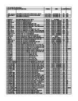
COMPARISON OF HYDROMATIC® BRAKE MODELS The following is a list, by size, of earlier designed Parkersburg® Hydromatic® brake models, and later designed Parmac L.L.C. Hydromatic® brake models, that replace the earlier Parkersburg brake models. Due to improvements in design the new models are smaller and lighter and have more braking capacity at the same brake speeds than the earlier Parkersburg models. All Hydromatic brake models, except the 481, are provided as clockwise or counter clockwise rotation, and shaft diameters and lengths to meet the customer’s requirements. Parkersburg Old Models None None 15” SR (Obsolete) 15” DR None 22” SR 22” DR None None 40” SR (Obsolete) 46” SR (Obsolete) None 60” SR (Obsolete) None
Parmac L.L.C. New Models 111-300 112-500 121 122 201 202 V-80 SSR28 262 341 342 451 481 and V-200 V-295
The 111-300 and 112-500 brakes are for heat generation applications, such as nitrogen vaporization units, and are not suitable for winches, or retarding applications. The 121 and 122, require different cradles for mounting, than the 15”SR and 15”DR. The 202 contains the same mounting dimensions, and shaft sizes as the 22”SR and will install in an existing 22”SR cradle. The V-80 requires a different cradle for mounting , than the 22”DR. The 341 and 341-A contain the same mounting dimensions, and shaft sizes as the models of 40”SR and will install in an existing 40”SR cradle. The 342 and 342-A contain the same mounting dimensions, and shaft sizes as the models of 46”SR and will install in an existing 46”SR cradle. The 481 or V-200 contain the same mounting dimensions, and shaft sizes as the models of 60”SR and will install in an existing 60”SR cradle. 18
TABLE 4 HYDROMATIC® BRAKES OR HYDROTARDERS® *
** Maximum
Maximum
Maximum
Volume
Weight of
Pressure P.S.I.
Speed RPM
Shaft Dia. Inches
In Gallons
Brake Pounds
Capacity Horsepower
111-300
25
2300
1 3/4
1
180
300
112-500
25
2300
2
3
265
500
15 DR
25
2300
3 1/8
6
580
1600
121
25
2300
3 1/8
2
300
800
122
25
2300
3 1/8
3 1/4
432
1600
201
25
1550
5
5
980
1500
22 SR
25
1550
4 15/16
10
1200
2500
202
25
1550
5
9 1/10
1475
3000
22 DR
25
1550
4 5/16
20
2300
4000
V-80
15
1550
5
13 1/2
1240
5000
SSR28
15
900
5
17
2120
5500
262
15
850
5 1/2
30
2650
6000
341
15
600
7 1/2
35
3400
6000
341A
15
600
7 1/2
35
2465
6000
! 40 SR
15
570
7 1/2
68
3400
6000
342
15
600
7 1/2
56
5300
7500
342A
15
600
7 1/2
56
3900
7500
! 46 SR
15
500
7 1/2
80
5000
7000
! 60 SR
15
375
7 1/2
180
9500
8000
451
15
500
7 1/2
78
3700
8500
481
15
450
7 1/2
98
7500
9000
V200
15
480
7 1/2
96
9100
10000
V295
15
350
9 1/4
315
26880
12000
SIZE
Brakes are furnished with special shafts to customers specifications up to the maximum shaft diameter shown. ! Obsolete Models * Based upon maximum possible fluid flowrate thru the brake. ** Based upon maximum rotor RPM and attainable at a flowrate and horsepower less than maximum.
19
INSTALLATION DIMENSIONS 111-300 HYDROMATIC® BRAKE
112-500 HYDROMATIC® BRAKE
20
INSTALLATION DIMENSIONS 121 HYDROMATIC® BRAKE
122 HYDROMATIC® BRAKE
21
INSTALLATION DIMENSIONS 15"DR HYDROMATIC® BRAKE
22"SR HYDROMATIC® BRAKE
22
INSTALLATION DIMENSIONS 201 HYDROMATIC® BRAKE
202 HYDROMATIC® BRAKE
23
INSTALLATION DIMENSIONS V-80 HYDROMATIC® BRAKE
22DR HYDROMATIC® BRAKE
24
INSTALLATION DIMENSIONS SSR28 HYDROMATIC® BRAKE
262 HYDROMATIC® BRAKE
25
INSTALLATION DIMENSIONS 341 HYDROMATIC® BRAKE
40"SR HYDROMATIC® BRAKE
26
INSTALLATION DIMENSIONS 342 HYDROMATIC® BRAKE
46"SR HYDROMATIC® BRAKE
27
INSTALLATION DIMENSIONS 481 HYDROMATIC® BRAKE
60"SR HYDROMATIC® BRAKE
28
INSTALLATION DIMENSIONS
451 HYDROMATIC® BRAKE
V-200 HYDROMATIC® BRAKE
29
INSTALLATION DIMENSIONS V-295 HYDROMATIC® BRAKE
30
111-300 Brake Torque Full Brake Performance
Parmac L.L.C. Coffeyville, Kansas
Reference Drawing U632834
800 750
60 GPM
700 650
50 GPM
600
40 GPM
500 450 400
NO PUMP
350
SUPPLY PUMP FLOWRATE
BRAKE TORQUE Lbs. Ft.
550
300 250 200 150 100 50 0
0
100
200
300
400
500
600
700
800
900
1000 1100 1200 1300 1400 1500 1600 1700 1800 1900 2000 2100 2200 2300
BRAKE RPM 31
Minimum Inlet Pressure - 10 PSI
Parmac L.L.C. Coffeyville, Kansas
111-300 Brake Horsepower Full Brake Performance
Reference Drawing U632835
320
60 GPM
300 280
50 GPM
260 240
40 GPM
200 180
NO PUMP
160
SUPPLY PUMP FLOWRATE
BRAKE HORSEPOWER
220
140 120 100 80 60 40 20 0
0
100
200
300
400
500
600
700
800
900
1000 1100 1200 1300 1400 1500 1600 1700 1800 1900 2000 2100 2200 2300
BRAKE RPM 32
Minimum Inlet Pressure - 10 PSI
112-500 Brake Torque Full Brake Performance
Parmac L.L.C. Coffeyville, Kansas
Reference Drawing U632960
1,600 1,500 1,400 1,300 1,200
BRAKE TORQUE Lbs. Ft.
1,100 1,000 900 800 700 600 500 400 300 200 100 0
0
100
200
300
400
500
600
700
800
900
1000 1100 1200 1300 1400 1500 1600 1700 1800 1900 2000 2100 2200 2300
BRAKE RPM 33
Parmac L.L.C. Coffeyville, Kansas
112-500 Brake Horsepower Full Brake Performance
Reference Drawing U632961
600 560 520 480
BRAKE HORSEPOWER
440 400 360 320 280 240 200 160 120 80 40 0
0
100
200
300
400
500
600
700
800
900
1000 1100 1200 1300 1400 1500 1600 1700 1800 1900 2000 2100 2200 2300
BRAKE RPM 34
MAX SPEED 2300 1550 1550
HORSEPOWER 15"DR - 22"SR - 22"DR HYDROMATIC BRAKES
HYDROMATIC BRAKE 15 DR 22 SR 22 DR
MAX HORSEPOWER 1,600 2,500 4,000
3,000
2,000 1,500
NOTE: Above Maximum Speed at Maximum Horsepower, horsepower will remain constant, torque will decrease. NOTE: These are maximum performance curves with full brake. For less power absorption ( in area above curves) water flow may be varied, giving less horsepower or torque at higher RPM.
BRAKE SPEED - RPM
1,000 900 800 700
DR 15
600 500 400
22 300
SR
DR 22
200
100 10
20
30
40 50
70
100
300
200
HORSEPOWER 35
500
700
1,000
2,000
3,000
5,000 7,000
U632097
3,000
SPEED 1885 895 830
TORQUE - 15DR-22SR-22DR HYDROMATIC BRAKES
MAX HYDROMATIC TORQUE BRAKE 4,450 15 DR 14,670 22 SR 25,300 22 DR
2,000 1,500
NOTE: Above Maximum Speed at Maximum Horsepower, horsepower will remain constant, torque will decrease. NOTE: These are maximum performance curves with full brake. For less power absorption ( in area above curves) water flow may be varied, giving less horsepower or torque at higher RPM.
BRAKE SPEED - RPM
1,000 900 800 700
15
DR
600 500 400
SR 22
300
22
200
100 100
200
300 400 500
700
1,000
DR
2,000
3,000
5,000
TORQUE - LBS. FT.
36
10,000
20,000
30,000
50,000 70,000
U632098
MAX SPEED 2300 2300 1550 1550 1550 900
MAX HORSEPOWER 800 1,600 1,500 3,000 5,000 5,500
HORSEPOWER 121 - 122 - 201 - 202 - V80 - SSR28 HYDROMATIC BRAKES
HYDROMATIC BRAKE 121 122 201 202 V-80 SSR28
NOTE: Above Maximum Speed at Maximum Horsepower, horsepower will remain constant, torque will decrease. NOTE: These are the maximum performance curves with full brake, For less power absorption ( in area above curves) water flow may be varied, giving less horsepower or torque at higher RPM.
3,000
2,000 1,500
BRAKE SPEED - RPM
1,000 900 800 700
12
1
12
600
2
500 400
1 20
300
20
200
100 10
20
30
40 50
70
100
2
SSR
0 V-8
28
300
200
HORSEPOWER
37
500
700
1,000
2,000
3,000
5,000 7,000
U632099
SPEED 1585 1585 885 885 825 700
TORQUE 121-122-201-202-V-80-SSR28 HYDROMATIC BRAKES
3,000
MAX HYDROMATIC TORQUE BRAKE 2,650 121 5,300 122 8,880 201 17,760 202 31,820 V-80 41,115 SSR28
NOTE: Above Maximum Speed at Maximum Horsepower, horsepower will remain constant, torque will decrease. NOTE: These are the maximum performance curves with full brake, For less power absorption ( in area above curves) water flow may be varied, giving less horsepower or torque at higher RPM.
2,000 1,500
2 12
1 12
BRAKE SPEED - RPM
1,000 900 800 700 600
80 V-
500 400 300
8 R2 S S
2 20
1 20
200
100 100
200
300 400 500
700
1,000
2,000
3,000
5,000
TORQUE - LBS. FT.
38
10,000
20,000
30,000
50,000 70,000
U632100
1,000 900 800 700 600 500 400
BRAKE SPEED - RPM
200
1 45
100 90 80 70 60
NOTE: Above Maximum Speed at Maximum Horsepower, Horsepower will remain constant, torque will decrease.
50
NOTE: These are maximum performance curves with full brake. For less power absorption ( in area above curves) water flow may be varied, giving less horsepower or torque at higher RPM.
40 30
20
10 10
HYDROMATIC BRAKE 451
20
30
40 50
70
100
300
200
HORSEPOWER
39
500
700
1,000
2,000
MAX MAX SPEED HORSEPOWER 8500 500
3,000
5,000
U632105
10,000
HORSEPOWER - 451 HYDROMATIC® BRAKE
300
1,000 900 800 700 600 500 400 300
BRAKE SPEED - RPM
1 45
100 90 80 70 60
NOTE: Above Maximum Speed at Maximum Horsepower, Horsepower will remain constant, torque will decrease.
50
NOTE: These are maximum performance curves with full brake. For less power absorption ( in area above curves) water flow may be varied, giving less horsepower or torque at higher RPM.
40 30
20
HYDROMATIC BRAKE 451 10 1000
2000
3000
5000
10,000
20,000 30,000
50,000
TORQUE - LBS. FT
40
100,000
MAX TORQUE 135025
200,000
SPEED 330
500,000
U632106
TORQUE - 451 HYDROMATIC® BRAKE
200
600 500
HYDROMATIC BRAKE 262 341-341A 342-342A 481 V-200 V-295
MAX SPEED 850 600 600 450 480 350
MAX HORSEPOWER 6,000 6,000 7,500 9,000 10,000 12,000
NOTE: Above Maximum Speed at Maximum Horsepower horsepower will remain constant, torque will decrease NOTE: These are maximum performance curves with a full brake. For less power absorption (in area above curves) water flow may be varied, giving less horsepower or torque at higher RPM.
400 300
26
2
481
A 342 2 34
1A - 34 1 4 3
00 V-2
95 V-2
100 90 80 70 60 50 40 30
10 10
20
30
40 50
70
100
300
200
HORSEPOWER 41
500
700
1,000
2,000
3,000
5,000
U632101 & U632107
12,000
20
10,000
BRAKE SPEED - RPM
200
HORSEPOWER 262- 341-341A-342-342A-481-V-200-V-295 HYDROMATIC BRAKES
1,000 900 800 700
NOTE: Above Maximum Speed at Maximum Horsepower horsepower will remain constant, torque will decrease NOTE: These are maximum performance curves with a full brake. For less power absorption (in area above curves) water flow may be varied, giving less horsepower or torque at higher RPM.
600 500
HYDROMATIC MAX BRAKE TORQUE
400
2 26
300
1A 34 1 34
200
BRAKE SPEED - RPM
262 341-341A 342-342A 481 V-200 V-295
A 42 3 234 100 90 80 70
48
2 V-
47,173 65,345 98,205 156,935 215,725 449,665
SPEED 670 480 400 300 240 140
00
1
60
2 V-
50
95
40 30
20
10 1000
2000
3000
5000
10,000
20,000 30,000
50,000
TORQUE - LBS. FT
42
100,000
200,000
500,000 U632102 & U632108
TORQUE 262-341-341A-342-342A-481-V-200-V-295 HYDROMATIC BRAKES
1,000 900 800 700
600
HYDROMATIC BRAKE 36"SR 40"SR 46"SR 60"SR
MAX SPEED 635 570 500 375
MAX HORSEPOWER 5,000 6,000 7,000 8,000
NOTE: Above Maximum Speed at Maximum Horsepower horsepower will remain constant, torque will decrease
HORSEPOWER 36"SR - 40"SR - 46"SR - 60"SR HYDROMATIC BRAKES
1,000 900 800 700
NOTE: These are maximum performance curves with a full brake. For less power absorption (in area above curves) water flow may be varied, giving less horsepower or torque at higher RPM.
500 400 300
BRAKE SPEED - RPM
200
SR 36" SR 40" SR 46" SR 60"
100 90 80 70 60 50 40 30
20
10 10
20
30
40 50
70
100
300
200
HORSEPOWER 43
500
700
1,000
2,000
3,000
5,000
U632103
10,000
1,000 900 800 700
NOTE: Above Maximum Speed at Maximum Horsepower horsepower will remain constant, torque will decrease
500
HYDROMATIC MAX BRAKE TORQUE
400
R "S 6 3
300
40
200
BRAKE SPEED - RPM
46
"S
"S
36"SR 40"SR 46"SR 60"SR
R
47,610 66.425 93,590 132,340
R
R "S 0 6
100 90 80 70 60 50 40 30
20
10 1000
2000
3000
5000
10,000
20,000 30,000
50,000
TORQUE - LBS. FT
44
100,000
200,000
500,000 U632104
SPEED 550 470 390 315
TORQUE 36"SR - 40"SR - 46"SR - 60"SR HYDROMATIC BRAKES
NOTE: These are maximum performance curves with a full brake. For less power absorption (in area above curves) water flow may be varied, giving less horsepower or torque at higher RPM.
600
PARMAC SALES OFFICES MAIN OFFICE & MANUFACTURING PLANT PARMAC L.L.C. P.O. BOX 1149 201 EAST 12TH STREET COFFEYVILLE, KANSAS 67337-0917 – U.S.A. PHONE: 620-251-5000 FAX: 620-251-0225 EMAIL: [email protected] WEBSITE: www.parmacbrake.com Call Forwarding Locations Calls are forwarded to PARMAC L.L.C., Coffeyville, KS ODESSA, TEXAS (432) 332-6433
HOUSTON, TEXAS (713) 956-7400
OKLAHOMA CITY, OKLAHOMA (405) 634-1417
SALES REPRESENTATIVE CANADA Harco Developments Ltd 51520 Range Road 214 Sherwood Park Alberta, T8E 1H2 Canada 1-780-922-3604 “PARMAC HYDROMATIC® BRAKES are produced under one or more of the following United States Patents.” 1,746,372 1,992,911 2,126,751 2,786,552 4,043,434 1,915,547 1,992,912 2,170,128 3,016,991 4,755,947 1,985,889 2,061,866 2,287,130 3,860,097 5,289,905 1,992,910 2,113,109 2,733,778 3,945,473 PARKERSBURG® HYDROMATIC® BRAKES are produced under the following Foreign Patents. Argentine Patents 42,776, 204,561, 210,301 Venezuelan patents 1494/33, 34,203 34,898, 37,294 D.R.P. Patent 642,008 Italian Patents 499,982, 1,026,328, 1,053,427 Ned. Octrooi, 41246, 42587, 165538 Mexican Patents 138,767, 144,116 Germany Patent 25 01 019
French Patents 1,078,520, 75.00279, 77 11001, 76.01328 British Patents 421,807, 422,264, 724,293 1,485,551, 1,571,699 Canadian Patents 557,393, 1,030,841, 1,058,053 Australian Patent 491,681, 514-850 Brazil Patents 7,702,267, 7,500,215 Austria Patent 366,158 Japan Patent 1,198,213
Trademarks HYDROMATIC, HYDROTARDER, and PARKERSBURG registered in U.S.A. and Foreign Countries. © 2010 PARMAC L.L.C.
45
PRINTED IN U.S.A.