Section 7
GPSA Engineering Data Book 14th Edition REVISION 0 DATE REASON(S) FOR REVISION 4/1/2017 Initial release GPSA Engi
Views 295 Downloads 4 File size 178KB
Recommend stories


- Author / Uploaded
- Asad Khan
Citation preview
GPSA Engineering Data Book 14th Edition
REVISION
0
DATE
REASON(S) FOR REVISION
4/1/2017 Initial release
GPSA Engineering Data Book 14th Edition
A Amesh
= area, ft2
FIG. 7-1 Nomenclature MW =
= Mesh pad area, ft2
NILL
Ap
= particle or droplet cross sectional area, ft 2
NLL
= =
C' D Dc Dh Dp
= = = = =
Nref Nμ OD P QA
= = = = =
d2 d95
= Nozzel diamter, ft = Droplet size (micron) for 95% removal
Q1 Q1,max
= =
g
= acceleration due to gravity, 32.2 ft/sec2
R
=
= Gas-oil ratio
Re
=
= Height, ft
Stk
=
= = = = =
T t V Vc Vh
= = = = =
V1
=
Vr Vr,max
= =
= seam to seam length of vessel, ft
Vt
=
= Effective gravity droplet settling length for a horizontal separator, ft
Wg
=
GOR H Hset HILL HHILL HLL HHLL J K KCR L Lset LILL LLILL LLL LLLL Mp
drag coefficient of particle, dimensionless (Fig. 7-3) Vessel diamter, ft Characteristic diameter in Stoke Number, St Liquid hydraulic diameter, ft droplet diameter, ft
Settling height, ft High interphase liquid level High- high interphase liquid level High liquid level High- high liquid level
= gas momentum, lb/(ft•sec2) = empirical constant for separator sizing, ft/sec = proportionality constant from Fig. 7-4 for use in Eq 7-5, dimensionless
= = = =
Low interphase liquid level Low-low interphase liquid level Low liquid level Low-low liquid level
= mass of droplet or particle, lb
W1 = Z = Greek β ρc
=
ρg
= =
ρl
=
ρhl
=
ρll
=
ρm
=
ρp μc
= =
μg μhl
= =
μll μ1 σ φ
= = = =
The sample calculations, equations and spreadsheets presented herein were developed using examples published in the Enginee While every effort has been made to present accurate and reliable technical information and calculation spreadsheets based on t The Calculation Spreadsheets are provided without warranty of any kind including warranties of accuracy or reasonableness of In no event will the GPA or GPSA and their members be liable for any damages whatsoever (including without limitation, those These calculation spreadsheets are provided to provide an “Operational level” of accuracy calculation based on rather broad ass
7-1 clature molecular weight, lb/lb mole Normal interphase liquid level Normal liquid level Reynolds film number Interfacial viscosity number Outside diamter, in system pressure, psia actual gas flow rate, ft3/sec Liquid volumetric flow rate, ft3/min Maximum liquid volumetric flow rate, ft 3/min gas constant, 10.73 (psia•ft3)(°R•lb mole) Reynolds number, dimensionless Dimensionless Stokes Number: [g • pc • Vc • D2p]/(18μc • Dc) system temperature, °R retention time, minutes Velocity, ft/sec Velocity of continuous phase, ft/sec Flow vapor velocity between gas-liquid interphase and the top of a horizontal separator, ft/sec Liquid velocity, ft/sec Gas velocity relative to liquid, ft/sec Maximum velocity of a gas relative to liquid to resist substantial re-entreainment critical or terminal gas velocity necessary for particles of size D p to drop or settle out of gas, ft/sec Flow rate of gas, lb/hr Flow rate of liquid, lb/hr compressibility factor, dimensionless
Greek Ratio of the number of influent particles of a given size to the number of effluent particles of the same size Continuous phase density, lb/ft3 gas phase density, lb/ft3 liquid phase density, droplet or particle, lb/ft 3
Heavy liquid phase density, lb/ft3 Light liquid phase density, lb/ft3 Mixed fluid density, lb/ft3 Droplet or partical phase density, lb/ft 3 viscosity of continuous pase, Cp Gas viscosity, cP Heavy liquid phase viscosity, cP Light liquid phase viscosity, cP Liquid viscosity, cP Liquid surface tension, dynes/cm Flow parameter
eloped using examples published in the Engineering Data Book as published by the Gas Processors Suppliers Association as a service to the ormation and calculation spreadsheets based on the GPSA Engineering Data Book sample calculations, the use of such information is volunt ing warranties of accuracy or reasonableness of factual or scientific assumptions, studies or conclusions, or merchantability, fitness for a pa whatsoever (including without limitation, those resulting from lost profits, lost data or business interruption) arising from the use, inability of accuracy calculation based on rather broad assumptions (including but not limited to: temperatures, pressures, compositions, imperial cur
sociation as a service to the gas processing industry. All information and calculation formulae has been compiled and edited in cooperation such information is voluntary and the GPA and GPSA do not guarantee the accuracy, completeness, efficacy, or timeliness of such informa hantability, fitness for a particular purpose, or non-infringement of intellectual property. sing from the use, inability to, reference to or reliance on the information in this Publication, whether based on warranty, contract, tort or an compositions, imperial curves, site conditions etc) and do not replace detailed and accurate Design Engineering taking into account actual p
and edited in cooperation with Gas Processors Association (GPA). meliness of such information. Reference herein to any specific commercial product, calculation method, process, or service by trade-name
arranty, contract, tort or any other legal theory and whether or not advised of the possibility of such damages. king into account actual process conditions, fluid properties, equipment condition or fowling and actual control set-point dead-band limitati
or service by trade-name, trademark, and service mark manufacturer or otherwise does not constitute or imply endorsement, recommendati
t-point dead-band limitations.
dorsement, recommendation or favoring by the GPA and/or GPSA.
GPSA Engineering Data Book 14th Edition
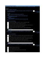
Example 7-1 -- Calculate the terminal velocity using the drag coefficient and Stokes' Law terminal settling velocity in a vertical gas-liquid separator for a 150 micron particle for a fluid with the physical properties listed below.
Given: ρg μg
=
ρl Dp
=
Dp
=
150*0.00003937/12=0.000492
C' (Re) C' Vt
= =
0.95*10 2.07*(0.000492 •(31.2 - 2.07)/0.012 =4741 1.35 (4*32.2*0.000492*(31.2-2.07)/(3*2.07*1.35))0.5=0.47
= =
2.07 0.012
lb/ft3 cP
31.2 150
lb/ft3 microns
Calculations: 2
=
8*
3
ft 2
ft/sec
The sample calculations, equations and spreadsheets presented herein were developed using examples published in the Enginee While every effort has been made to present accurate and reliable technical information and calculation spreadsheets based on t The Calculation Spreadsheets are provided without warranty of any kind including warranties of accuracy or reasonableness of In no event will the GPA or GPSA and their members be liable for any damages whatsoever (including without limitation, those These calculation spreadsheets are provided to provide an “Operational level” of accuracy calculation based on rather broad ass
aw terminal settling velocity in a perties listed below.
Application 7-1 -- Calculate the terminal velocity using the drag coefficient and Stokes in a vertical gas-liquid separator for a 150 micron particle for a fluid with the physical
Given: ρg μg
=
ρl Dp
= =
31.2 150
Dp
=
0.000492
C' (Re) C' Vt
= =
4,741 1.35 0.47
=
2.07 0.012
Calculations: (from Eq. 7-4) (from Fig.7-5) (from Eq. 7-1)
2
=
g examples published in the Engineering Data Book as published by the Gas Processors Suppliers Association as a service to the gas process calculation spreadsheets based on the GPSA Engineering Data Book sample calculations, the use of such information is voluntary and the es of accuracy or reasonableness of factual or scientific assumptions, studies or conclusions, or merchantability, fitness for a particular purp (including without limitation, those resulting from lost profits, lost data or business interruption) arising from the use, inability to, referenc calculation based on rather broad assumptions (including but not limited to: temperatures, pressures, compositions, imperial curves, site con
using the drag coefficient and Stokes' Law terminal settling velocity particle for a fluid with the physical properties listed below.
lb/ft3 cP lb/ft3 microns ft (from Eq. 7-4) (from Fig.7-5) ft/sec
(from Eq. 7-1)
sociation as a service to the gas processing industry. All information and calculation formulae has been compiled and edited in cooperation such information is voluntary and the GPA and GPSA do not guarantee the accuracy, completeness, efficacy, or timeliness of such informat hantability, fitness for a particular purpose, or non-infringement of intellectual property. sing from the use, inability to, reference to or reliance on the information in this Publication, whether based on warranty, contract, tort or an compositions, imperial curves, site conditions etc) and do not replace detailed and accurate Design Engineering taking into account actual p
piled and edited in cooperation with Gas Processors Association (GPA). y, or timeliness of such information. Reference herein to any specific commercial product, calculation method, process, or service by trade-
on warranty, contract, tort or any other legal theory and whether or not advised of the possibility of such damages. ing taking into account actual process conditions, fluid properties, equipment condition or fowling and actual control set-point dead-band li
ocess, or service by trade-name, trademark, and service mark manufacturer or otherwise does not constitute or imply endorsement, recomme
rol set-point dead-band limitations.
ply endorsement, recommendation or favoring by the GPA and/or GPSA.
GPSA Engineering Data Book 14th Edition
Example 7-2 -- Determine the size of a vertical gas-liquid separator with a high efficiency wire mesh mist eliminator to h gas and 100 gpm of condensate. A design factor of 10% will be used. Operating Conditions and Design Gas molecular weight Operating temperature Operating pressure Gas flowrate Liquid flowrate Design Factor Souder-Brown K-value Inlet device Internals Vapor outlet configuration Allowance for support ring Inlet piping OD Inlet piping ID Bottom tangent to LLLL LLLL to LL surge time LLL to HLL surge time HLL to HHLL surge time
= = = = = = = = = = = = = = = = =
17.55 120 500 150 100 10% 0.35 Diffuser Mist eliminator Nozzle above top head 4.00 18.00 16.876 18.0 1.0 5.0 1.0
Physical Properties ρg = μg =
1.552 0.013
ρl = μl =
44.68 0.574
ρm =
1.75
Vessel Diameter Sizing Wg = Wl = QA = Corrected K-value = Vmax =
17.55*150*1000000/24/379.47=289054 100*60/7.4805*44.68=35837 289054/1.552/3600*(1+0.1)=56.91 0.82*0.35=0.29 0.29*SQRT((44.68-1.552)/1.552)=1.51
D =
(4*56.91/3.1416/1.51)0.5+4/12=7.26
A =
3.14159*(7.5/2)^2=44.2
Liquid Surge Section Q = LLL to HLL = LLLL to LLL =
35837/44.68/60*(1+0.1)=14.7 14.7/44.2*5*12=20.0 14.7/44.2*1*12=4.0
HLL to HHLL = LLLL to HHLL =
14.7/44.2*1*12=4.0 (20+4+4)/12=2.3
Check De-Gassing (200 micron bubble) V1 = 14.7/44.2/60=0.006 Vt = 1.145/1000*(44.68-1.552)/0.574=0.086 De-Gassing: can occur Check Inlet Velocity Head for Nozzle size V = (289054+35837)*144/1.75/3.1416/(16.876/2)^2/3600=33.2 J = 1.75*33.2^2=1929 Vessel Lengths H1 + H2 = 18/12+2.5=4.0 H3 = 2.00 H4 = 1.50 H5 = 3.00 H6 = 0.50 H7 = 7.26/4=1.82 use 2.0 Demister to Oulet Nozzle = 7.5/2-16.876/2/12=3.05 Total Vessel Length = 4+2+1.5+3+0.5+2=13.0
The sample calculations, equations and spreadsheets presented herein were developed using examples published in the Enginee While every effort has been made to present accurate and reliable technical information and calculation spreadsheets based on t The Calculation Spreadsheets are provided without warranty of any kind including warranties of accuracy or reasonableness of In no event will the GPA or GPSA and their members be liable for any damages whatsoever (including without limitation, those These calculation spreadsheets are provided to provide an “Operational level” of accuracy calculation based on rather broad ass
wire mesh mist eliminator to handle 150 MMSCFD (MW= 17.55) of
lbm/lbmole °F psig MMSCFD gpm ft/sec (Figure 7-35a) (Figure 7-38) inch inch inch inch min min min
lb/ft3 cP lb/ft3 cP lb/ft3 lb/hr lb/hr ft3/sec ft/sec ft/sec
(K is corrected for pressure using Fig. 7-36) (Equation 7-11)
ft
(Equation 7-18, rounded up to 7.5 ft)
ft
2
ft3/min inch inch
inch ft
(rounded up to 2.5 ft)
ft/sec ft/sec
Equation 7-16a Equation 7-17
ft/sec lb/ft•sec2
acceptable
ft ft ft ft ft ft ft ft
(bottom tangent to HHLL) (HHLL to Feed nozzle bottom) (Feed nozzle diameter) (Feed nozzle top to mist eliminator bottom) (Feed nozzle top to mist eliminator bottom) (per Fig. 6-23 for elliptical 2:1 heads) (Figure 7-38) (total length tangent-to-tangent)
amples published in the Engineering Data Book as published by the Gas Processors Suppliers Association as a service to the gas processing lculation spreadsheets based on the GPSA Engineering Data Book sample calculations, the use of such information is voluntary and the GPA of accuracy or reasonableness of factual or scientific assumptions, studies or conclusions, or merchantability, fitness for a particular purpose ncluding without limitation, those resulting from lost profits, lost data or business interruption) arising from the use, inability to, reference to ulation based on rather broad assumptions (including but not limited to: temperatures, pressures, compositions, imperial curves, site conditi
Application 7-2 -- Determine the size of a vertical gas-liquid separator with a high efficiency wire mesh mist eliminator t gas and 100 gpm of condensate. A design factor of 10% will be used. Operating Conditions and Design Gas molecular weight Operating temperature Operating pressure Gas flowrate Liquid flowrate Design Factor Souder-Brown K-value Inlet device Internals Vapor outlet configuration Allowance for support ring Inlet piping OD Inlet piping ID Bottom tangent to LLLL LLLL to LL surge time LLL to HLL surge time HLL to HHLL surge time
= = = = = = = = = = = = = = = = =
17.55 120 500 150 100 10% 0.35 Diffuser Mist eliminator Nozzle above top head 4.00 18.00 16.876 18.0 1.0 5.0 1.0
lbm/lbmole °F psig MMSCFD gpm ft/sec
inch inch inch inch min min min
Physical Properties ρg = μg =
1.552 0.013
lb/ft3 cP
ρl μl
= =
44.68 0.574
lb/ft3 cP
ρm
=
1.75
lb/ft3
Wg Wl QA Corrected K-value Vmax
= = = = =
289,054 35,837 56.91 0.29 1.51
lb/hr lb/hr ft3/sec ft/sec ft/sec
D
=
7.50
ft
A
=
44.2
ft2
Q
= = =
14.70 20.0 4.0
ft3/min inch inch
Vessel Diameter Sizing
Liquid Surge Section LLL to HLL LLLL to LLL
= =
4.0 2.5
inch ft
Vt
= =
ft/sec ft/sec
De-Gassing: Check Inlet Velocity Head for Nozzle size V J
0.006 0.086 can occur
= =
33.2
ft/sec
1,929
lb/ft•sec2
= = = = = = = =
4.00 2.00 1.50 3.00 0.50 2.00 3.05 13.00
ft ft ft ft ft ft ft ft
HLL to HHLL LLLL to HHLL Check De-Gassing (200 micron bubble)
V1
Vessel Lengths H1 + H2 H3 H4 H5 H6 H7 Demister to Oulet Nozzle Total Vessel Length
Gas Processors Suppliers Association as a service to the gas processing industry. All information and calculation formulae has been compil mple calculations, the use of such information is voluntary and the GPA and GPSA do not guarantee the accuracy, completeness, efficacy, o udies or conclusions, or merchantability, fitness for a particular purpose, or non-infringement of intellectual property. a or business interruption) arising from the use, inability to, reference to or reliance on the information in this Publication, whether based on to: temperatures, pressures, compositions, imperial curves, site conditions etc) and do not replace detailed and accurate Design Engineering
ficiency wire mesh mist eliminator to handle 150 MMSCFD (MW= 17.55) of
(Figure 7-35a) (Figure 7-38)
(K is corrected for pressure using Fig. 7-36) (Equation 7-11) (Equation 7-18, rounded up to 0.5 ft)
Equation 7-16a Equation 7-17
acceptable (bottom tangent to HHLL) (HHLL to Feed nozzle bottom) (Feed nozzle diameter) (Feed nozzle top to mist eliminator bottom) (Feed nozzle top to mist eliminator bottom) (per Fig. 6-23 for elliptical 2:1 heads) (Figure 7-38) (total length tangent-to-tangent)
calculation formulae has been compiled and edited in cooperation with Gas Processors Association (GPA). he accuracy, completeness, efficacy, or timeliness of such information. Reference herein to any specific commercial product, calculation m ectual property. in this Publication, whether based on warranty, contract, tort or any other legal theory and whether or not advised of the possibility of such ailed and accurate Design Engineering taking into account actual process conditions, fluid properties, equipment condition or fowling and a
commercial product, calculation method, process, or service by trade-name, trademark, and service mark manufacturer or otherwise does no
t advised of the possibility of such damages. ipment condition or fowling and actual control set-point dead-band limitations.
turer or otherwise does not constitute or imply endorsement, recommendation or favoring by the GPA and/or GPSA.
K values FPS K values SI Inlet device 0.35 0.11 Diffuser 0.40 0.12 Baffle 0.45 0.14 Elbow 0.50 0.15 Half-pipe 0.55 0.17 Cyclone 0.60 0.18 None 0.65 0.20 0.70 0.21 0.75 0.23 0.80 0.24 0.85 0.26 0.90 0.27 0.95 0.29 1.00 0.30
Outlet config. Nozzle above top head Side nozzle above demister Side nozzle below demister
Internals Mist eliminator
GPSA Engineering Data Book 14th Edition
Application 7-3 -- Determine the configuration and size of a separator vessel to provide surge upstream of a process unit of condensate and 15 MMSCFD of gas (MW = 17.55). Process conditions are as follows: Operating Conditions -Operating temperature Operating pressure Gas flowrate Liquid flowrate Physical Properties --
ρg μg ρl μ1 ρm Gas MW
= = = = = = = = = =
Project Surge Times -LLLL to LLL = LLLL to NLL = LLL to HLL = HLL to HHLL = Assumptions for vessel sizing -Type = Design driven by = Inlet nozzle type = LLLL height = Length/Diameter ratio = Assumed partial volume to LLLL = Assumed partial volume to HHLL = Inlet nozzle ID = Outlet gas nozzle ID = Flow rates -Gas flowrate = Liquid flowrate = Vessel sizing -- Including the liquid volume stored in the vessel's heads Surge time = Total volume of vessel = Vessel internal diameter = Vessel length (tangent-to tangent) = Liquid Level Calculation -H/D at LLLL = Calculated partial volume to LLLL =
Partial volume to LLLL height = Surge volume (LLLL to HHLL) = Partial volume to HHLL height = Volume fraction to HHLL height = H/D at HHLL = HHLL height = Volume fraction at NLL = H/D at NLL = NLL height = Check Gas flow factor @ HHLL in Gravity Separation Section -Gas flow area = Average gas velocity = Flow factor = Check De-Gassing -De-gassing = Calculate Mesh Pad Area & Height -K factor for high efficiency eliminator = De-rated K factor = Vmax = Amesh = Check Nozzles Head -Inlet nozzle velocity
=
Inlet nozzle momentum
=
Inlet nozzle size
=
Outlet gas nozzle velocity
=
Outlet gas nozzle momentum
=
Outlet gas nozzle size
=
The sample calculations, equations and spreadsheets presented herein were developed using examples published in the Enginee While every effort has been made to present accurate and reliable technical information and calculation spreadsheets based on t The Calculation Spreadsheets are provided without warranty of any kind including warranties of accuracy or reasonableness of In no event will the GPA or GPSA and their members be liable for any damages whatsoever (including without limitation, those These calculation spreadsheets are provided to provide an “Operational level” of accuracy calculation based on rather broad ass
guration and size of a separator vessel to provide surge upstream of a process unit and to separate liquids and gas. The stream is 25 (MW = 17.55). Process conditions are as follows: 120 250 15
°F, psig MMSCFD
25,000
bpd
0.774
lb/ft3
0.012 44.58 0.573
lb/ft3 lb/ft3 cP
6.87 17.55
lb/ft3 lb/lbmol
1.0 3.5 5.0 1.0 horizontal high liquid flowrate diffuser 18.00 3.00 10% 70% 10.020 6.065
15*1000000/24/379.47*17.55=28905 25000*5.615/24*44.58=260747 ume stored in the vessel's heads 1+5+1=7 260747/60/44.58*7/(0.70-0.10)=1137 4*1137/3.1416/3/(1+1/(3*3))0.333=7.6 8*3.0=24 18/12/8=0.1875 13%
min min min min
inches
inches inches lb/hr lb/hr min ft3 ft ft
0.13*1137=143 (0.70-0.10)*1137=682 143+682=826 826/1137*100=73% 0.679 0.679*8=5.43 25000*5.615/1440*3.5/1137+0.13=0.426 0.443 0.443*8=3.54 avity Separation Section -(1-0.73)*3.14159*(8/2)2=13.8 28905/0.774/13.8/3600=0.75 0.75*((44.58-0.774)/0.774)-0.5=0.100
ft3 ft3 ft3
ft
ft ft2 ft/sec ft/sec
Not an issue 0.35 0.89*0.35=0.31 0.31*SQRT(44.58/0.774-1)=2.35 28905/0.774/3600/2.35=4.41 (28905+260747)*144*1/(6.87*1*3.14159*(10.02/2)2*3600)=21.4 6.87*21.42=3142
ft/sec ft/sec ft/sec ft2 ft/sec lb/ft•sec2
Acceptable 28905*144*1/0.774/1/3.14159/(6.065/2)2/3600=51.7 0.774*51.7 =2069 2
ft/sec lb/ft•sec2
Acceptable
preadsheets presented herein were developed using examples published in the Engineering Data Book as published by the Gas Processors S ent accurate and reliable technical information and calculation spreadsheets based on the GPSA Engineering Data Book sample calculation ed without warranty of any kind including warranties of accuracy or reasonableness of factual or scientific assumptions, studies or conclusio eir members be liable for any damages whatsoever (including without limitation, those resulting from lost profits, lost data or business inte ded to provide an “Operational level” of accuracy calculation based on rather broad assumptions (including but not limited to: temperatures
nit and to separate liquids and gas. The stream is 25,000 bpd
Application 7-3 -- Determine the configuration and size of a se The stream is 25,000 bpd of condensate and 15 MMSCFD of g Operating Conditions -Operating temperature Operating pressure Gas flowrate Liquid flowrate Physical Properties --
ρg μg ρl μ1 ρm Gas MW
Project Surge Times -LLLL to LLL LLLL to NLL LLL to HLL HLL to HHLL
(7 min surging from LLLL to HHLL) Assumptions for vessel sizing --
Type Design driven by Inlet nozzle type LLLL height Length/Diameter ratio Assumed partial volume to LLLL Assumed partial volume to HHLL Inlet nozzle ID Outlet gas nozzle ID Flow rates -0.1260469816
(rounded up to 8 ft)
(using Figs. 6-24 & 6-25 w/H/D=0.1875)
Gas flowrate Liquid flowrate Vessel sizing -- Including the liquid volume stored in the vessel's Surge time Total vessel capacity Vessel internal diameter Vessel length (tangent-to tangent) Liquid Level Calculation -H/D at LLLL Calculated partial volume to LLLL
(using Figs. 6-24 & 6-25)
(using Figs. 6-24 & 6-25 w/H/D=0.426)
(Acceptable gas area, flow factor 2 min)
(with help from Fig.7-36) (Equation 7-11)
Partial volume to LLLL height Surge volume (LLLL to HHLL) Partial volume to HHLL height Volume fraction to HHLL height H/D at HHLL HHLL height Volume fraction at NLL H/D at NLL NLL height Check Gas flow factor @ HHLL in Gravity Separation Sectio Gas flow area Average gas velocity Flow factor Check De-Gassing -De-gassing Calculate Mesh Pad Area & Height -K factor for high efficiency eliminator De-rated K factor Vmax Amesh
(Equation 7-13) Check Nozzles Head --
Inlet nozzle velocity Inlet nozzle momentum (momentum