Operation Manual of KPD100 Controller 20130731
KPD100 Controller Operation Manual R WUXI KIPOR POWER 1 O Model KPD100 2 AUTO www.kipor.com Version No.:KPD100.1
Views 197 Downloads 15 File size 482KB
Recommend stories


- Author / Uploaded
- Ramon Palacios
Citation preview
KPD100 Controller Operation Manual
R
WUXI KIPOR POWER
1
O
Model KPD100
2
AUTO
www.kipor.com Version No.:KPD100.1.1.3
CONTENT CONTENT............................................................................................................................................................... BRIEF INTRODUCTION.................................................................................................................................... 1 CONTROLLER OUTLINE AND WIRING TERMINAL..................................................................................1 1. CONTROLLER OUTLINE..............................................................................................................................1 2. BACK OUTLINE AND OVERALL DIMENSION(UNIT:MM)................................................................ 2 3. WIRING TERMINAL OF CONTROLLER.................................................................................................... 3 OPERATION.........................................................................................................................................................4 1. MANUAL MODE.............................................................................................................................................. 4 2. AUTO MODE....................................................................................................................................................5 3 SWITCH LOAD MANUALLY........................................................................................................................5 4. SKIP DELAY.....................................................................................................................................................6 5. OPERATION SEQUENCE FIGURE............................................................................................................ 6 PROTECTION...................................................................................................................................................... 7 1. ALARMING INFORMATION.......................................................................................................................... 8 2. SHUT DOWN INFORMATION...................................................................................................................... 9 3.TROUBLESHOOTING.................................................................................................................................. 10 4. STATUS INDICATOR FOR POWER GRID AND GENERATOR.......................................................... 10 PARAMETER SETTING.................................................................................................................................. 10 REMOTE START/ANALOG POWER GRID................................................................................................ 14 REMOTE START SETTING AND GENSET STATUS................................................................................14 REMOTE MONITORIN.....................................................................................................................................15 1. MONITORING SOFTWARE........................................................................................................................15 2. COMMUNICATION ADDRESS...................................................................................................................16 RS232 COMMUNICATION..............................................................................................................................17 1. PHYSICAL LAYER FOR COMMUNICATION PROTOCOL...................................................................17 2. ASYNCHRONOUS SERIAL COMMUNICATION.................................................................................... 18 3. CODE TABLE................................................................................................................................................ 18 APPENDIX 1.CRC16-CCITT DATA SHEET................................................................................................ 19 APPENDIX 2.CRC16-CCITT CODE GENERATION METHOD............................................................... 20 APPENDIX 3. OPERATION DATA................................................................................................................ 21 APPENDIX 4. WIRING.....................................................................................................................................22 1. 3-PHASE 4-LINE...........................................................................................................................................22 2. 3-PHASE 3-LINE...........................................................................................................................................23 3. 1-PHASE 2-LINE...........................................................................................................................................23
-I-
- II -
KPD100 Controller Operation Manual
Brief Introduction: KPD100 controller can monitor the power grid. When power grid is abnormal, genset can be started automatically and supply power to the load. When power grid is restored, it will be transfered to grid supply automatically. KPD100 controller can monitor the power grid and indicate power grid status by iuminous diode. Features: 1:Control and protection: Realize genset manual or auto start, shut down, ATS switch and alarming protection. 2:12V/24VDC power supply; 3:Manual and auto working modes for selection; 4:AMFpower grid failure self-start/shut down; 5:Root-mean-square voltage of generator and power grid can be inspected; 6:ATS manual/ auto mode; 7:Self-maintenance function with interval setting available; 8:luminous diode failure display; 9:Engine underspeed/overspeed protection 10:Configurable input/output terminal and status indicating function; 11:Battery voltage checking and battery cahrging inspection; 12:Working time counting function 13:RS232 communication. PC can realize parameter setting and monitoring.
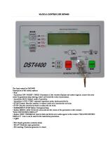
Controller outline and wiring terminal 1. Controller outline Front :
R
WUXI KIPOR POWER
Power grid abnormal Power grid normal Red:Abnormal Green:Normal
ATS/load power supply indicator lamp Left: Power grid Right: Genset
1
O
Model KPD100
2
Fault, system parameter display
Genset normal Genset abnormal Red:abnormal Green:normal
AUTO
Auto mode Indicator lamp
Control panel alarming symbol description: —— Low oil pressure
—— High water temperature
-1-
—— Low fuel level
KPD100 Controller Operation Manual
—— Over speed of engine
——Under speed of engine
—— Battery charging failure !1—— Configurable input 1 alarming
—— Genset start failure !2—— Configurable input 2 alarming
Functions of buttons: During genset running, press Stop/Parameter decreasing Key
In alarming status, press
to stop the genset, to reset.
In ”Parameter setting” mode, press the key to decrease value. Manual start/Parameter increasing key Auto/Parameter plus key
Manual/Paramete r saving key
In “manual mode”, press
can start the genset.
In ”Parameter setting” mode, press the key to increase value. Press
to set the genset in Auto Mode.
In “System Setting mode” , press this key to increase the data value, equal to “+” In “Auto” mode, press
to set the genset in manual mode.
In manual mode, press this key to switch load between power supplies. In “System Setting mode”, press this key to save the data, equal to “OK”.
Note: ¾ After the controller is powered, ¾
Work mode will set to be “Manual Mode
¾
“Power grid voltage abnormal indicator” will be lit if there is no input of MAINS or power grid is in abnormal situation. If the default setting of ATS is “Power grid power supply”, “Switch on terminal of power grid 34,35”is closed, “Indicator for power grid with load” will be illuminated.
¾
” automatically
2. Back outline and overall dimension(Unit:mm)
-2-
KPD100 Controller Operation Manual
3. Wiring terminal of controller Terminal code
Function
Remark
1
Not be used
2
Aux_Input2
Auxiliary input2 ※1
3
Aux_Input1
Auxiliary input1 ※1
4
Remote Start
Remote start input
5
Fuel Level
Switch input of fuel level
6
Engine Temp
Switch input of cooling temperature
7
Oil Press
Switch input of oil pressure
8
Not be used
9
CHANGE IN
Input end of charging failure
10
AUX1_NC
Auxiliary output 2 normally closed contact
11
AUX1
12
AUX1_NO
Auxiliary output 2normally open contact
13
CRANK_NC
Normally closed contact for starting relay output
14
CRANK_COM
Public end for starting relay output
15
CRANK_NO
Normally open contact for starting relay output
16
FUEL_NC
Normally closed contact for fuel relay output
17
FUEL_COM
Public end for fuel relay output
18
FUEL_NO
Normally open contact for fuel relay output
19
GND
DC working power negative pole:B-
20
VCC
DC working power positive pole:B+
21
COMM_TXD
RS232 communication
22
COMM_RXD
23
COMM_GND
24
COMM_VCC
25
AUX2_NC
Normally closed contact for Auxiliary output 1
26
AUX2_COM
Public end for Auxiliary output 1 ※2
27
AUX2_NO
Normally open contact for Auxiliary output 1
_COM
28
Auxiliary output 2 public end ※2
DC12/24V
Not be used
29
GENSET_NC
Normally closed contact for genset switch on output
30
GENSET_COM
Public end for genset switch on output
31
GENSET_NO
Normally open contact for genset switch on output
32
Not be used
33
MAINS_NC
Normally closed contact for power grid switch on output
34
MAINS_COM
Public end for power grid switch on output
35
MAINS_NO
Normally open contact for power grid switch on output
36 37
Not be used GEN_VOL_N
38 39
Not be used GEN_VOL_A
40 41 42
N-phase input for genset A-phase monitoring input for genset Not be used
MAINS_VOL_N
N-phase input for power grid Not be used -3-
KPD100 Controller Operation Manual 43
MAINS_VOL_C
44
C-phase monitoring input for power grid Not be used
45
MAINS_VOL_B
46
B-phase monitoring input for power grid Not be used
47
MAINS_VOL_A
A-phase monitoring input for power grid
※ 1:Refer to “input configuration” for details ※ 2: Refer to “output configuration” for details
Operation There are two kinds of working modes for controller: Manual mode and auto mode. In manual mode, press the button on the front panel of the controller to start the genset, shut down the genset and switch the power supply for loads. In auto mode, controller will monitor the power grid. When power grid is in abnormal situation, genset will be started automatically and genset will supply power to the loads. When power grid returns to normal, load supply will be switched to mains supply.
1. Manual mode (1) Get into manual mode Manual mode can be access by the following methods: (1) The system will get into manual mode once controller is powered; (2) When in auto mode,press
“Manual” key to enter manual mode.
(3) When in auto mode, press
“Stop” key to enter manual mode.
(4) Set the button on the back of panel from parameter configuration to running status, system can get into manual mode. (2) Operate the genset manually Press
“Manual start” key to start the genset manually and system will get into manual mode:
If preheat output option of auxiliary output is selected, start the preheat hour meter and enable the auxiliary output signal effective. Engine will be started after the preheat delay is terminated.The maximum starting time for starting motor is 10 seconds. Perform a second try after 10 seconds if the first start is failed. If the genset cannot be started in three times, starting fails and related indicator will be lit. Engine is started successfully when 20Hz AC current is detected or the effective time of oil pressure signal reaches rated value(configurable). And starting motor is tripped. Safety delay countdown (12 seconds) starts after successful engine start. During safety delay, low oil pressure, high water temperature, under speed and battery charging failure is permissable. Warm-up timer starts once genset voltage and frequency is normal. Ensure the stability of engine performance before connected with load. Genset will run without load after warm-up delay. If main power supply is abnormal or remote start -4-
KPD100 Controller Operation Manual signal is effective and it is configured as remoter start with load, load will be switched to genset. The genset will continue to run with load regardless of power supply and remote start signal input status until auto mode is selected. If auto mode is selected at present, power supply is in normal situation and remote start signal is invalid, load will be switched to power grid and cooling shut-down delay starts. Cooling and shut down will be followed. Press
“Stop” key to shut down the engine.
2. Auto mode Press
“Auto” key to enter auto mode and related indicator lamp is lit.
In auto mode, genset cannot be started by pressing
key.
Genset start delay timer will be started to prevent momentary failure of power grid supply or false remote start signal. Genset will be started after the delay. If preheat output option of auxiliary output is selected, start the preheat hour meter and enable the auxiliary output signal effective. Engine will be started after the preheat delay is terminated.The maximum starting time for starting motor is 10 seconds. Perform a second try after 10 seconds if the first start is failed. If the genset cannot be started in three times, starting fails and related indicator will be lit. Engine is started successfully when 20Hz AC current is detected or the effective time of oil pressure signal reaches rated value(configurable). And starting motor is tripped. Safety delay countdown (12 seconds) starts after successful engine start. During safety delay, low oil pressure, high water temperature, under speed and battery charging failure is permissable. Warm-up timer starts once genset voltage and frequency is normal. Ensure the stability of engine performance before connected with load. Genset will run without load after warm-up delay. If main power supply is abnormal or remote start signal is effective and it is configured as remoter start with load, load will be switched to genset. If power grid supply is restored, power grid return delay starts. Load will be transfered to the grid after the delay. Then cooling delay will start to ensure the engine cooling before shut down. If power supply is abnormal (or remote starting signal is effective) during the engine cooling, load will be transfered to genset immediately.
3. Switch load manually Controller can swith loads manually. In manual mode, press In auto mode, press will be off. Press
“Manual” key to switch load power supply manually. “Manual” key to enter manual working mode. Indicator lamp of auto mode
“Manual” key at this moment to switch load manually.
-5-
KPD100 Controller Operation Manual
4. Skip d`elay In suto mode, press
“Auto” key or input of skip delay is effective, the following delays can be
skipped: 1.Genset start delay 2.Power grid return delay 3.Genset warm-up delay Corresponding actions can be performed direcly if the above delays are skipped. This function cannot cover other delays.
5. Operation sequence figure
Note: Description of delays: Starting delay ------ When the failure or remote start signal sent by power grid is effective, “genset start delay” countdown starts. If the power gird is normal and remote start signal is invalid during the countdown, the countdown will be reset. Genset will be started when countdown terminates as well as controller is in auto mode. This delay can prevent power grid transient fluctutation and misstart caused by false remote start signal. Preheat delay ------ If “Preheat delay” of configurable output 1 & 2 is selceted, this output is effective when genset is started and controller will start “Preheat delay” countdown. Safety delay ------ During safety delay (12 seconds), protective function for low oil pressure, high water temperature, under speed and battery charging failure does not work. Warm-up delay ------ When genset is started successfully and parameters are normal, controller will start “genset warm-up delay” countdown. If genset paramters are abnormal or shut down failure occurs during the this period, countdown will be reset.Genset can be availabe after the countdown. In auto mode, when power grid is abnormal or remote start with load is effective(remote start signal is valid and remote start with load is configured),load will be switched to genset power supply. This delay ensure the genset with load after stable operation. Return delay ------ To prevent momentary recovery of power grid. Cooling delay ------ In auto mode, load is transfered from genset power supply to power grid supply, -6-
KPD100 Controller Operation Manual controller will start “genset cooling shut down delay” countdown. If power gird is abnormal or remote start with load is effective during this period, the countdown will be reset. Load will be switched to genset supply. Genset will be stopped after the countdown. This delay enable the genset to stop after the cooling. Power grid return delay ------ Controller will start “power grid return delay” countdown. If power grid fails during this period, the countdown will be reset. Power gird will be restored after the countdwn. When in auto mode, remote start with load is invalid(remote start signal is invalid or system is configured as remote start without load), load will be transfered to power grid supply. Shut down output delay ------
If “Shut down output” of configurable output 1 & 2 is selceted, this
output will be effective when the engine shut down. When the delay is terminated or genset is resarted, this output is invalid. Power switch delay ------ Main contactor of transfer switch responses promptly which enbale the attenuation of voltage produced by the inductive load before connected with power supply. Starting oil pressure delay ----- If low oil pressure signal is invalid during the genset start, controller will start “successful start oil pressure delay” countdown. If low oil pressure signal is effecitive during the countdown, the countdown will be reset.If 20Hz AC current is detected during the countdown, genset is started successfully and countdown will be reset. Countdown will be terminated after successful start. 2. Delay time setting depends on the actual situation.
Protection R
WUXI KIPOR POWER
1
O
Model KPD100
2
AUTO
Controller has protective functions to prevent genset against damage, when genst is in abnormal situations: ¾ Controller can send alarming information, related LED indicator lamp is illuminated or twinkles. ¾
When ATS is in “Auto mode
”, it can be switched to “Manual mode
-7-
” automatically.
KPD100 Controller Operation Manual ¾
ATS power supply is switched to “power grid power supply” automatically.
¾
When it sends “alarming” information, alarming LED indicator lamp is illuminated.
¾
When it sends “Shut down” information, alarming LED indicator lamp twinkles.
1. Alarming information Alarming fault: warning but do not shut-down. Related red luminous diode is illuminated. Warning items: Over/under voltage of battery voltage Charging failure of battery Low fuel level Under voltage(Configured as warning alarm) Over voltage(Configured as warning alarm) Under frequency(Configured as warning alarm) Configurable input 1 (Configured as warning alarm) Configurable input 2(Configured as warning alarm) ¾
Over/under voltage of battery voltage
● If battery voltage is detected too low, battery will be discharged and the battery LED fault indicator lamp
is illuminated.
● If battery voltage is detected too high, battery will be charged and battery LED fault indicator lamp is illuminated. ¾
Charging failure of battery
When battery voltage is lower than charging failure voltage and discharge current is higher than 2A, or when charging failure switch signal is detected, battery failure LED indicator lamp ¾
Low fuel level When “Low fuel level” signal is detected, low fuel level LED indicator lamp
¾
is illuminated.
is illuminated.
Under frequency When “Low frequency” is detected, under frequency LED indicator lamp
is illuminated.
Note: Configurable parameter 22# (Shut down due to under speed)is set as “No”. ¾
Over voltage When high voltage is detected, generator abnormal indicator lamp (red) is illuminated.
¾
Under voltage When low voltage is detected, generator abnormal indicator lamp (red) is illuminated.
Configurable parameter 24# (Shut down due to over voltage),23#(Shut down due to under voltage)is set as “No”. ¾
Configurable input 1,2 alarming When warning alarming is configured, if the inspection value of auxiliary input interface exceeds the setting value, configurable input indicator lamp (!1or !2)is lit -8-
KPD100 Controller Operation Manual
2. Shut down information Genset will be shut down in case of shut down failures. Meanwhile failures will be saved and locked automatically. Related luminous diode flashes. Shut down items: Starting failure Low oil pressure High water temperature Under voltage(configured as shut down alarming) Over voltage(configured as shut down alarming) Under frequency(configured as shut down alarming) Over frequency Configurable input 1(configured as shut down alarming) Configurable input 2 (configured as shut down alarming) ¾
Starting failure
If the engine cannot be started in specified period, starting failure LED indicator
flashed and
genset will be stopped. ¾
Low oil pressure
If low oil pressure signal is deteced after 12s safety delay, low oil pressure LED indicator flashes and genset will be shut down. If low oil pressure signal is detected during 12s safety delay, low oil pressure LED indicator
is lit,
genset will not be stopped. Genset will be shut down immediately after delay. ¾
High water temperature
If high water temperature signal is deteced after safety delay, high water temperature LED indicator flashes and genset will be shut down. If high water temperature signal is detected during 12s safety delay, high water temperature LED indicator ¾
is lit, genset will not be stopped. Genset will be shut down immediately after delay.
Over voltage
If genset voltage is detected too high, genset abnormal indicator(red) will be lit and genset will be shut down. ¾
Under voltage
If genset voltage is detected too low, genset abnormal indicator(red) will be lit and genset will be shut down. Note: Configurable parameter 24#(shut down due to over voltage),23#(shut down due to under voltage) is set as “YES” ¾
Under frequency
If engine frequency is detected too low, under frequency LED indicator shut down. -9-
flashes, genset will be
KPD100 Controller Operation Manual Note: Configurable parameter 22#(shut down due to under speed) is set as “YES”. ¾
Over frequency
If genset frequency is detected too high beyond or within safety delay, over frequency LED indicator flashes, genset will be shut down. ¾
Configurable input 1,2 alarming
When shut down alarming is configured, if the inspection value of configurable input interface 1 or 2 exceeds the setting value, configurable input indicator lamp (!1or !2) flashes, and genset will be shut down.
3. Troubleshooting Relevant LED indicator lamp will be on if generator is faulty. Press
to shut down the generator when in abnormal situation.
Engine will be stopped if failures occur. If alarming indicator lamp is lit or flashes,press
key to
elimnate the failure indication and controller will be in standby.
4. Status indicator for power grid and generator If the voltage(or frequency) of power grid (or generator)is detected too high or too low, the power grid (genset) abnormal indicator lamp (red) on the panel is illuminated. The lamp is green in normal situation.
Parameter setting Set the switch behind the controller to the “setting” position to enter system parameter setting.
- 10 -
KPD100 Controller Operation Manual After entering system setting mode, auto mode indicator lamp on the front panel twinkles, and luminous diode indicates the values. See the below figure:
R
WUXI KIPOR POWER
Model KPD100
Code 1
2
Parameter
O
Press
[Parameter decrease] and
[Parameter + ] to set values. Press
AUTO
[Parameter increase] key to switch data, press [Save] to save the data. Parameter table
Ref.
1
Parameter
Alternator winding
Parameter code
○○○○○
2
Rated frequency
○○○○●
3
Rated voltage sheet
○○○●○
4
Rated voltage
Remark (Bold fonts are
Value code
regarded as default value )
○○○
Three phase four line system
○○●
Three phase three line system
○●○
single phase two line system
○○○
50Hz
○○●
60Hz
○○○
Sheet 1 ↓
○○●
○○○●●
- 11 -
Sheet 2 ↓
○○○
100V
230V
○○●
110V
240V
○●○
115V
255V
○●●
120V
277V
●○○
127V
277V
●○●
133V
277V
●●○
139V
277V
●●●
220V
277V
KPD100 Controller Operation Manual
Power gird voltage is low(%rated 5
voltage)(Trip
○○●○○
value/returned value)
Power gird voltage is 6
high(%rated
○○●○●
voltage)(Returned value/trip value)
Genset
voltage
is
low(%rated 7
voltage)(Trip
○○●●○
value/returned value)
Genset 8
voltage
is
high(%rated voltage)(Returned
○○●●●
value/trip value)
Genset
start
delay(Prevent misstart caused by 9
power
grid
○●○○○
momentary fluctuation )
- 12 -
○○○
95%
/ 90%
○○●
95%
/ 85%
○●○
95%
/ 80%
○●●
95%
/ 70%
●○○
90%
/ 90%
●○●
90%
/ 85%
●●○
90%
/ 80%
●●●
90%
/ 70%
○○○
105%
/
110%
○○●
105%
/
115%
○●○
105%
/
120%
○●●
105%
/
130%
●○○
110% /
110%
●○●
110% /
115%
●●○
110% /
120%
●●●
110% /
130%
○○○
95%
/ 90%
○○●
95%
/ 85%
○●○
95%
/ 80%
○●●
95%
/ 70%
●○○
90%
/ 90%
●○●
90%
/ 85%
●●○
90%
/ 80%
●●●
90%
/ 70%
○○○
105%
/
110%
○○●
105%
/
115%
○●○
105%
/
120%
○●●
105%
/
130%
●○○
110% /
110%
●○●
110% /
115%
●●○
110% /
120%
●●●
110% /
130%
○○○
0s
○○●
1s
○●○
3s
○●●
5s
●○○
3h
●○●
4h
●●○
6h
●●●
8h
KPD100 Controller Operation Manual ○○○
0s
○○●
5s
○●○
10s
○●●
15s
●○○
20s
●○●
30s
●●○
60s
●●●
180s
○○○
0s
○○●
1s
○●○
2s
○●●
3s
●○○
4s
●○●
5s
●●○
6s
●●●
8s
○○○
0s
warm-up
○○●
1s
delay( Ensure the
○●○
2s
○●●
3s
●○○
5s
●○●
30s
●●○
120s
●●●
300s
○○○
0m
○○●
0.1m(For testing)
○●○
2m
○●●
5m
●○○
10m
●○●
15m
●●○
25m
●●●
30m
○○○
0s
○○●
5s
○●○
10s
○●●
15s
●○○
20s
●○●
30s
●●○
60s
●●●
180s
Normal
delay
power 10
for grid
return(prevent temporary
○●○○● power
grid recovery)
Genset 11
preheat
delay
(If
“Preheat
delay”
is
effective
when
○●○●○
selected,
delay starting motor)
Genset
12
genset can connect with load after stable
○●○●●
running)
Genset 13
delay(Shut
cooling down
○●●○○
after cooling delay)
Shut
down
delay(“shut 14
output down
output” is effective
○●●○●
when selected, it is invalid after delay)
- 13 -
KPD100 Controller Operation Manual
15
Power switch delay
○○○
0s
(Control
main
○○●
1s
contact of transfer
○●○
2s
○●●
3s
●○○
4s
inductive load before
●○●
5s
connected
●●○
8s
●●●
10s
○○○
12V
○○●
24V
○○○
9V
the
○○●
10V
genset run normally,
○●○
12V
○●●
14V
●○○
22V
setting
●○●
24V
value, then it will be
●●○
26V
charge alarm)
●●●
28V
○○○
Normal open
○○●
Normal close
○○○
Normal close
○○●
Normal open
○○○
Normal open
○○●
Normal close
○○○
Reserved
○○●
0s
○●○
0.2s
○●●
0.5s
●○○
0.8s
●○●
1.0s
●●○
1.5s
●●●
2.0s
○○○
No
○○●
Yes
○○○
No
○○●
Yes
○○○
No
○○●
Yes
○○○
Reserved
○○●
Remote start normal open
switch,reduce
the
voltage produced by
○●●●○
with
power supply.) 16
Battery voltage
○●●●●
Charge voltage(when
17
if the detect value of charge lower
voltage than
is
●○○○○
18
Low pressure
●○○○●
19
High water temp.
●○○●○
20
Low fuel level
●○○●●
21
Delay
time
for
starting oil pressure
●○●○○
22
Low speed stop run
●○●○●
23
Low voltage stop run
●○●●○
24 25
Over voltage stop run Remote function
start
●○●●● ●●○○○
- 14 -
KPD100 Controller Operation Manual
26
27
28
29
30
31
Remote on-load
Input 1
Input 2
Output 1
Output 2
Communication address
start
●●○○●
●●○●○
●●○●●
●●●●○
●●●○●
●●●●○
- 15 -
○●○
Remote start normal close
○●●
Mains start normal open
●○○
Mains start normal close
○○○
No
○○●
Yes
○○○
Immediately alarm open
○○●
Immediately alarm close
○●○
Immediately stop open
○●●
Immediately stop close
●○○
Delay alarm open
●○●
Delay alarm close
●●○
Delay stop open
●●●
Delay stop close
○○○
Immediately alarm open
○○●
Immediately alarm close
○●○
Immediately stop open
○●●
Immediately stop close
●○○
Delay alarm open
●○●
Delay alarm close
●●○
Delay stop open
●●●
Delay stop close
○○○
Reserved
○○●
Preheat
○●○
Genset run
○●●
System warn alarm
●○○
System stop alarm
●○●
System alarm
●●○
System automatic mode
●●●
Stop output
○○○
Ats Invain
○○●
Preheat
○●○
Genset run
○●●
System warn alarm
●○○
System stop alarm
●○●
System alarm
●●○
System automatic mode
●●●
Stop output
○○○
0
○○●
1
○●○
2
KPD100 Controller Operation Manual
32
Maintenance interval
●●●●●
○●●
3
●○○
4
●○●
5
●●○
6
●●●
7
○○○
Reserved
○○●
One week
○●○
Two weeks
○●●
Three weeks
●○○
Four weeks
●○●
Five weeks
●●○
Six weeks
●●●
Seven weeks
Remote start/Analog power grid Remote start setting and genset status Parameter
Remote start(remote start with load is set unavailable)
Setting value
Mains status
Remote Mains start is supply is normally normal open
Genset start for terminal 4 high potential
Load switch
Genset start for terminal 4 low potential
Load switch
OFF Genset cannot start
No ON Genset start power supply for power grid
No power supply for power grid
Mains outage
ON Genset start
Yes Genset power supply
Yes Genset power supply
Remote Mains start is normal normally close
ON Genset start
No OFF power Genset cannot start supply for power grid
No power supply for power grid
Mains outage
ON Genset start
Yes Genset power supply
Yes Genset power supply
Analog Mains normal power grid is normally open
OFF Genset start
No OFF power Genset cannot start supply for power grid
- 16 -
ON Genset start
ON Genset start
No power supply for power grid
KPD100 Controller Operation Manual
Parameter
Setting value
Mains status
Genset start for terminal 4 high potential
Load switch
Genset start for terminal 4 low potential
Load switch
Analog Mains Remote outage start(remote power start with grid is load is set normally unavailable) open
ON Genset start
Yes Genset power supply
OFF Genset cannot start
No power supply for power grid
Analog Mains normal power grid is normally close Mains outage
OFF Genset start
No OFF power Genset cannot start supply for power grid
No power supply for power grid
OFF Genset start
No ON power Genset start supply for power grid
Yes
Remote Remote start(remote start is start with normally load is set open available)
Mains supply is normal
OFF Genset cannot start
No ON ower Genset start supply for power grid
Yes Genset power supply
Mains outage
ON Genset start
Yes Genset power supply
ON Genset start
Yes
ON Genset start
Yes Genset power supply
OFF Genset cannot start
No power supply for power grid
Mains outage
ON Genset start
Yes Genset power supply
ON Genset start
Yes Genset power supply
Mains supply is normal
OFF Genset cannot start
No OFF power Genset cannot start supply for power grid
No power supply for power grid
Mains outage
ON Genset start
Yes Genset power supply
No power supply for power grid
OFF Genset cannot start
No OFF power Genset cannot start supply for power grid
Remote Mains start is supply is normally normal close
Analog power grid is normally open
Genset power supply
Analog Mains power supply is grid is normal normally
- 17 -
Genset power supply
OFF Genset cannot start
No power supply for power grid
KPD100 Controller Operation Manual close
Mains outage
OFF Genset cannot start
ON No Genset start power supply for power grid
Yes Genset power supply
Remote monitoring KPD100 controller can be equipped with three-remote function to meet various needs: PC is connected with KPD100 controller via RS232 communication cable to realize three-remote function with the help of “KPD100 software”.: 100% Remote configuration,including running and fault status. 100% Remote measure the data, including all the measured data. 100% Remote control, covering all the control function for the control panel.
1. Monitoring software PC communication software “KPD100 software” can realize the following functions: Remote start/shut down Remote monitor Remote configurable parameters, including user’s parameters and system parameters(for administer authority). Remote monitoring software can be classified into “Administer” and “Operator” according to the authorities. “Administer” is used for the setting before delivery. Users can click the “OK” button on the initial interface of software directly to get into “User interface” without password. Refer to “KPD100 software operation manual” for detailed information.
2. Communication address Communication connection can only be available when “RS232 address” in the “KPD100 software” is the same with “RS232 communication address” of the KPD100 controller. (1) Default setting of KPD100 controller is “0”; (2) The setting for “RS232 address” in “KPD100 software”: Local setting - communication setting - communication port KPD100 Software drawing:
- 18 -
KPD100 Controller Operation Manual
COM address on PC
RS232 Communication The communication protocol applies for the serial communication between PC and controller RS232. PC and controller use the communication protocol in accordance with industrial control standard as well as main and slave machine mode. Main machine(PC) make a request and slave machine (controller) reply a message frame to perform data communication. Data frame
Frame header+address+code+data length+data+code+frame tail
Data length(Byte)
4
1
1
1
N
2
4
KPD100 controller can select communication software for upper computer and realize the following function by RS232 interface: Remote start/shut down Remote monitoring Remote configuration for user’s parameters and system parameters. Connection drawing for RS232 cable:
- 19 -
KPD100 Controller Operation Manual
1.Physical layer for communication protocol Communication physical link Communication interface Communication mode
EIA/TIA-232-E Asynchronous serial communication
Communication baud rate Odd-even check Start bit Data bits Stop bits Communication overtime
9600bps None 1 8 1 200ms
Bit1 Start bits
Bit2 D0
Bit3 D1
Bit4 D2
Bit5 D3
- 20 -
Bit6 D4
Bit7 D5
Bit8 D6
Bit9 D7
Bit10 Stop bits
KPD100 Controller Operation Manual
2. Asynchronous serial communication Serial communication protocol Data frame Frame header Communication address Code Data length Data Data verification
Frame tail
Data description 0xFA,0xA5,0xA 5,0xFA 1Byte
Data sequence
Low byte is in the front
1Byte 1Byte NByte
Low byte is in the front Low byte is in the front Low byte is in the front
2Byte/CRC16-C CITT verification 0xF5,0x5A,0x5 A,0xF5
High byte is in the front
Remark
Refer to code table for detailed code information, data length, data information. Refer to ATS operation manual for detailed algorithm
3. Code table Code Command code for main machine 0 1 2 3
Function
Data length
Shut down Manual mode Auto mode Configurable system parameters
4 Read system parameters 5 Write in current time 6 Read current time 7 Write in maintenance time 8 Read maintenance time 9 Read system running information Command code for slave machine - 21 -
Data
0 0 0 30 Refer to parameter configuration for details 0 6 Year month day hour minute second 0 4 Maintenance interval, day of week, hour, minute 0 0
KPD100 Controller Operation Manual
0 1 2 3
Shut down Manual mode Auto mode Configurable system parameters 4 Read system parameters 5 Write in current time 6 Read current time 7 Write in maintenance time 8 Read maintenance time 9 Read system running information
10 Module is in setting mode
the
Appendix 1.CRC16-CCITT Data sheet unsigned int CRC16CCITT[]= { 0x0000, 0x1021, 0x2042, 0x3063, 0x4084, 0x50a5, 0x60c6, 0x70e7, 0x8108, 0x9129, 0xa14a, 0xb16b, 0xc18c, 0xd1ad, 0xe1ce, 0xf1ef, 0x1231, 0x0210, 0x3273, 0x2252, 0x52b5, 0x4294, 0x72f7, 0x62d6, 0x9339, 0x8318, 0xb37b, 0xa35a, 0xd3bd, 0xc39c, 0xf3ff, 0xe3de, 0x2462, 0x3443, 0x0420, 0x1401, 0x64e6, 0x74c7, 0x44a4, 0x5485, 0xa56a, 0xb54b, 0x8528, 0x9509, 0xe5ee, 0xf5cf, 0xc5ac, 0xd58d, 0x3653, 0x2672, 0x1611, 0x0630, 0x76d7, 0x66f6, 0x5695, 0x46b4, 0xb75b, 0xa77a, 0x9719, 0x8738, 0xf7df, 0xe7fe, 0xd79d, 0xc7bc, 0x48c4, 0x58e5, 0x6886, 0x78a7, 0x0840, 0x1861, 0x2802, 0x3823, 0xc9cc, 0xd9ed, 0xe98e, 0xf9af, 0x8948, 0x9969, 0xa90a, 0xb92b, 0x5af5, 0x4ad4, 0x7ab7, 0x6a96, 0x1a71, 0x0a50, 0x3a33, 0x2a12, 0xdbfd, 0xcbdc, 0xfbbf, 0xeb9e, 0x9b79, 0x8b58, 0xbb3b, 0xab1a, 0x6ca6, 0x7c87, 0x4ce4, 0x5cc5, 0x2c22, 0x3c03, 0x0c60, 0x1c41, 0xedae, 0xfd8f, 0xcdec, 0xddcd, 0xad2a, 0xbd0b, 0x8d68, 0x9d49, 0x7e97, 0x6eb6, 0x5ed5, 0x4ef4, 0x3e13, 0x2e32, 0x1e51, 0x0e70, 0xff9f, 0xefbe, 0xdfdd, 0xcffc, 0xbf1b, 0xaf3a, 0x9f59, 0x8f78, 0x9188, 0x81a9, 0xb1ca, 0xa1eb, 0xd10c, 0xc12d, 0xf14e, 0xe16f, 0x1080, 0x00a1, 0x30c2, 0x20e3, 0x5004, 0x4025, 0x7046, 0x6067, 0x83b9, 0x9398, 0xa3fb, 0xb3da, 0xc33d, 0xd31c, 0xe37f, 0xf35e, 0x02b1, 0x1290, 0x22f3, 0x32d2, 0x4235, 0x5214, 0x6277, 0x7256, - 22 -
0 0 0 0 30 Refer to parameter configuration for details 0 6 0 5 52 Refer to system running information for details 0
KPD100 Controller Operation Manual 0xb5ea, 0xa5cb, 0x95a8, 0x8589, 0xf56e, 0xe54f, 0xd52c, 0xc50d, 0x34e2, 0x24c3, 0x14a0, 0x0481, 0x7466, 0x6447, 0x5424, 0x4405, 0xa7db, 0xb7fa, 0x8799, 0x97b8, 0xe75f, 0xf77e, 0xc71d, 0xd73c, 0x26d3, 0x36f2, 0x0691, 0x16b0, 0x6657, 0x7676, 0x4615, 0x5634, 0xd94c, 0xc96d, 0xf90e, 0xe92f, 0x99c8, 0x89e9, 0xb98a, 0xa9ab, 0x5844, 0x4865, 0x7806, 0x6827, 0x18c0, 0x08e1, 0x3882, 0x28a3, 0xcb7d, 0xdb5c, 0xeb3f, 0xfb1e, 0x8bf9, 0x9bd8, 0xabbb, 0xbb9a, 0x4a75, 0x5a54, 0x6a37, 0x7a16, 0x0af1, 0x1ad0, 0x2ab3, 0x3a92, 0xfd2e, 0xed0f, 0xdd6c, 0xcd4d, 0xbdaa, 0xad8b, 0x9de8, 0x8dc9, 0x7c26, 0x6c07, 0x5c64, 0x4c45, 0x3ca2, 0x2c83, 0x1ce0, 0x0cc1, 0xef1f, 0xff3e, 0xcf5d, 0xdf7c, 0xaf9b, 0xbfba, 0x8fd9, 0x9ff8, 0x6e17, 0x7e36, 0x4e55, 0x5e74, 0x2e93, 0x3eb2, 0x0ed1, 0x1ef0
};
Appendix 2.CRC16-CCITT Code generation method /******************************************************************* Function: Input:
Generate CRC16CCITT code p
= mouse cursor points to first byte
DataLen = Data length Output:
CRC16CCITT
*******************************************************************/ unsigned int CRC16CCITT(unsigned char *p,unsigned int DataLen) { unsigned int crc16=0; unsigned int i; unsigned char b; for(i=0;i>8); crc16