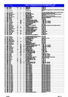
DIN 3971 1980-07 Bevel Gear Parameters
UDC 621.833.2:001.4 -:!.! July1980 DEUTSCHE NORMEN .: _:o.. DIN Definitions and Parameters for Bevel Gears and Be
Views 52 Downloads 0 File size 1MB
Recommend stories
- Author / Uploaded
- costa59dac9242
Citation preview
UDC 621.833.2:001.4
-:!.!
July1980
DEUTSCHE NORMEN
.:
_:o..
DIN
Definitions and Parameters for Bevel Gears and Bevel Gear Pairs
. . J:
.S.2~
.!! ~:;
.... .
3971
:>:C: -a~o
0
taC
&; ;::;
.,..,
Begriffe und Bestimmungsgrossen fiir Kegelrader und Kegelradpaare
.,
AC:"
•~c ._ C:GI
..... .... _... .........,
c: !§:! "'"' -~
.!: Cl;:!
at-;-;
~ .. .
.;
"'c: :::1
e
DIN 3999 DIN 7182 Part 1
0
z
...a .: . . z .. .s ~
;2
General definitions and parameters for gears, gear pairs and gear trains Denominations on gears and gear pairs; bevel and hypoid gears and gear pairs Symbols for gear teeth Tolerances and fits; fundamental terms
~
This Standard contains the definitions and symbols used for bevel gears and bevel gear pairs with intersecting axes as well as the definitions of the corresponding parameters . In addition, certain definitions relating to hypoid gear pairs are explained in Sections 5 and 8. The definitions and parameters contained in DIN 868, and which also apply to bevel gears and bevel gear pairs, are only explained when this appears necessary in the interests of a self-contained structure of this Standard. Apart from the definitions and parameters for external straight bevel gears, the corresponding parameters for helical and spiral bevel gears are indicated without, however, dealing with the special features of the various manufacturing processes.
., see Fig. 9. 3.4.4 Addendum modification, addendum modification coefficient xh If a standard basic rack tooth profile according to DIN 867 is used and if the datum line is not in the crown gear reference plane, it is usual to speak of addendum modification. The distance of the datum line from the crown gear reference plane is the addendum modification the magnitude of which is expressed by the addendum modification coefficient xh in fractions of the module mp: addendum modification= xh · mp. The coefficient xh is positive if the datum line is above the crown gear reference plane (outside the reference surface in the case of a bevel gear) and negative if it is below the crown gear reference plane (inside the reference surface in the case of a bevel gear), see Fig. 10 and Fig. 11.
DIN 3971 Page 9
Sp
I
Datum line
haP= h~. mp htp =hip· mp
h~
= ~1
hip = liP mp • 1t Spacewidth on the crown gear reference ep = -2-- circle ap =
hp = 2 • mp
haP= mp
mp•1t =ep=---
2 Other quantities as in Fig. 7
Flank angle
20°
sp
- h:p
+ cp Tooth depth
Figure 9. Standard basic rack tooth profile with tooth depth alteration
Addendum
h1p = mp + cp Dedendum Cp
= (0,1 ... 0,3) • mp Bottom clearance


