Chapter 2 Section Modulus Calculation
LNB 30503 Ship Structures TOPIC 3 SECTION MODULUS AND STRESS CALCULATION 4.1 SIMPLE BEAM THEORY The total bending m
Views 249 Downloads 3 File size 380KB
Recommend stories


- Author / Uploaded
- Umairah Azman
Citation preview
LNB 30503 Ship Structures
TOPIC 3
SECTION MODULUS AND STRESS CALCULATION
4.1
SIMPLE BEAM THEORY
The total bending moment or the stress is calculated by the simple beam theory using the relation
y
M M M or I Z I y
where
σ M I
stress at distance y from the neutral axis bending moment second moment of area
I/y will have its smallest value when y is greatest; that is when y is measured to the extreme fibres, at the deck and bottom (keel). This value of I/y or Z is called the section modulus and is the criterion of the strength of the girder in bending. In most cases the critical hull girder cross section will be that section which contains the least amount of effective material – that is, the section containing the Largest hatches or other openings but also depends on the distance of these from the neutral axis.
EXAMPLE 4.1 In example 3.4 in Chapter 3, if the ship has second moment of area of the midship section 576m4, neutral axis 4.5m from deck and 5.1m from keel, find section modulus of the midship section, and the location and value of where the maximum stress occurs.
Solution 4.1: From Example 3.4, bending moment at midship (station 5) is 9820.58 tonnes/m. Section modulus, Zkeel = I / y = 576m4 / 5.1m = 112.94m3 Section modulus, Zdeck= I / y = 576m4 / 4.5m = 128.00m3
LNB 30503
1
LNB 30503 Ship Structures
Stress at keel, keel
= M / Zkeel = 9820.58 tonnes/m / 112.94m3 = 86.95tonnes/m4
Stress at deck, deck
= M / Zdeck = 9820.58 tonnes/m / 128.00m3 = 76.72tonnes/m4
Maximum stress occurs at keel, keel = 86.95tonnes/m4. 4.2
THE NEUTRAL AXIS
Theoretical analysis shows that the neutral axis occurs exactly at the centre of gravity of the cross section of the object or beam. But with the plate and angle acting together as a beam the neutral axis is close to the plate. [NB. Material close to NA contributes little to the strength of a beam]
4.2.1 Neutral Axis of the Hull To locate the NA of the hull, designers once again look for the centre of gravity of the hull cross section. These include only on those parts or members of the hull structure that contribute directly to the bending strength of the hull girder i.e. members that run continuously fore and aft throughout at least the ship’s amidships half-length.
4.3
SECOND MOMENT OF AREA
The stiffness of a beam is directly influenced by a property of its cross sectional geometry that we call its second moment of area.
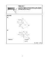
EXAMPLE 4.2 Calculate the second moment of area of the girder shown below.
LNB 30503
2
LNB 30503 Ship Structures
Solution 4.2
Item
Scantlings
Upper Flange
152mm x 25mm 203mm x 13mm 203mm x 25mm
Web Lower Flange
Area, a (mm2)
Height h (mm)
Moment of area ah (mm3)
2nd Moment of area ah2 (mm4)
Local 2nd Moment of area I (mm4)
3800
240.5
913900
219792950
197916.667
2639
126.5
333833.5
42229938
9062545.917
5075
12.5
63437.5
792969
264322.917
Σah = 1311171
Σah2 = 262815857
Σi = 9524785.5
Σa = 11514
Step 1 Centre of gravity or height of neutral axis above baseline: y=
ah 1311171 113.88mm 114mm a 11514
Step 2
I base i ah 2 9524785.5 262815856.5 272340642 mm 4
Step 3 I base I NA Ay 2 or I NA I base A(h NA ) 2 272340642 - 11514(114)2 122704698mm 4
LNB 30503
3
LNB 30503 Ship Structures
EXAMPLE 4.3 Calculate second moment of area at neutral axis and hence section modulus for deck and keel.
8m
22 mm
3m
16 mm
13 m
14 mm
18 mm 1.5 m
12 mm
20 mm
20 m
Solution 4.3 Since the cross section is symmetry about the centerline, it is adequate to carry out the calculation for one side of the ship and then double the resulting answer.
Item
Scantlings
Area, a (m2)
Height h (m)
Moment of area ah (m3)
Upperdeck
6m x 22mm
0.132
13
1.716
22.308
Local 2nd Moment of area i (m4) -
2nd Deck
6m x 16mm
0.096
10
0.960
9.600
-
Side Shell
13m x 14mm
0.182
6.5
1.183
7.689
2.563
Tank Top Bottom Shell Centre Girder
10m x 18mm
0.180
1.5
0.270
0.405
-
10m x 20mm
0.200
0.0
-
-
-
1.5m x 6mm
0.009
0.75
0.007
0.005
0.002
Σah = 4.136
Σah2 = 40.007
Σi = 2.565
Σa = 0.799
LNB 30503
2nd Moment of area ah2 (m4)
4
LNB 30503 Ship Structures
Step 1 Height of Neutral Axis above keel, ah 4.136 5.18m hNA a 0.799 Step 2 I base i ah 2
2.565 40.007 42.572 m 4 Step 3 I base I NA Ay 2
I NA A(h NA ) 2 or I NA I base A(h NA ) 2 42.572 - 0.799(5.18) 2 21.133 m 4 So, I NA (complete) 21.133 x 2 42.266 m 4
LNB 30503
5
LNB 30503 Ship Structures
EXAMPLE 4.4 The mass distribution and buoyancy between sections of a ship, 300m in length, balanced on a hogging wave, are given below. The second moment of area of the midship section is 752m4 and the neutral axis is 9.30m from the keel and 9.70m from the deck. Calculate the maximum direct stresses (keel and deck) given by the comparative calculation and the maximum sheer force and bending moment. Station
Mass / m (MN)
Buoyancy / m (MN)
0.88
0.005
1.609
0.025
2.093
0.714
3.082
3.038
2.56
5.684
3.064
6.368
3.237
4.929
3.489
2.445
2.22
0.498
1.645
0.106
1 2 3 4 5 6 7 8 9 10 11
LNB 30503
6
LNB 30503 Ship Structures
Solution 4.4 Station spacing = 300m / 10 = 30m Station
Mass/m MN
Buoyancy/m MN
Load/m MN
del SF MN
1
SF MN
mid SF MN
del BM MN
0 0.88
0.005
0.875
26.25
1.609
0.025
1.584
47.52
2.093
0.714
1.379
41.37
3.028
3.038
-0.01
-0.3
2.56
5.684
-3.124
-93.72
3.064
6.368
-3.304
-99.12
3.237
4.929
-1.692
-50.76
3.489
2.445
1.044
31.32
2.22
0.498
1.722
51.66
1.645
0.106
1.539
46.17
2
13.125
393.75
50.01
1500.3
94.455
2833.65
114.99
3449.7
67.98
2039.4
-28.44
-853.2
-103.38
-3101.4
-113.1
-3393
-71.61
-2148.3
-22.695
-680.85
26.25
3
73.77
4
115.14
5
8
-45.78
11
0.39
393.75
4.005
389.745
1894.05
8.01
1886.04
6262.2
-97.44
10
0
9363.6
-128.76
9
0
10216.8
-78
BM MNm
0
8177.4
21.12
7
corr
4727.7
114.84
6
BM MNm
12.015 4715.685 16.02
8161.38
20.025 10196.78 24.03
9339.57
28.035 6234.165
2869.2
32.04
2837.16
720.9
36.045
684.855
40.05
40.05
0
Maximum shear force = 128.76 MN Maximum bending moment = 10196.78 MNm =
M y I
Keel stress =
10196.78 MNm 9.3 m = 126.10MNm2 4 752 m
Deck stress =
10196.78MNm 9.7m = 131.53MNm2 4 752m
LNB 30503
7
LNB 30503 Ship Structures
4.4
SECTIONS WITH TWO MATERIALS
Some ships’ strength cross section is composed of two different materials. Typically the hull may be steel and the superstructure aluminum. Other materials used may be wood or reinforced plastic. In such a case it is convenient to think in terms of an effective modulus in one of the materials. Usually this would be in terms of steel. The stress, , in a beam at a point y from the NA is Ey/R, where E is the Young Modulus or Modulus of Elastic, and R is the radius of curvature. Provided transverse sections of the beam or ship remain plane, this relationship will hold as the extension or strain at any given y will be the same. For equilibrium of the section, the net force across it must be zero. Hence using the subscripts s and a for steel and aluminum: (sAs + aAa) = 0
and
E A y E A y s s s a a a 0 R R
that is:
E As y s a Aa y a 0 Es The corresponding bending moment is: BM
= (sAsys + aAaya) =
Es R
=
Es I E R
A y
s
2 s
Ea Aa y a2 Es
where IE is the effective second moment of area. The composite cross-section can therefore be considered made up of material s, usually steel, if an effective area of material a is used in place of the actual area. The effective area is the actual multiplied by the ratio Ea/Es. For different steels the ratio is effectively unity, for aluminum alloy/steel it is about 1/3 and for GRP/steel it is about 1/10.
4.5
SUPERSTRUCTURES
Superstructures and deckhouses are major discontinuities in the ship girder. They contribute to the longitudinal strength but will not be fully efficient in so doing. They should not be ignored as, although this would “play safe” in calculating the main hull strength, it would run the risk that the superstructure itself would not be strong enough to take the loads imposed on it at sea. Also they are potential sources of stress concentrations, particularly at their ends. For this reason they should not be ended close to highly stressed areas such as amidships. A superstructure is joined to the main hull at its lower boundary. As the ship sags or hogs the boundary becomes compressed and extended respectively. Thus the superstructure tends to be
LNB 30503
8
LNB 30503 Ship Structures
arched in the opposite shear forces due to the stretch or compression and normal forces trying to keep the two in contact. The ability of the superstructure to accept these forces, and contribute to the section modulus for longitudinal bending, is regarded as an efficiency. It is expressed as: Superstructure efficiency =
0 a 0
Where o, a and are the upper deck stresses if no superstructure were present, the stress calculated and that for a fully effective superstructure.
EXAMPLE 4.5 The midship section of a steel ship has the following particulars: Cross-sectional area of longitudinal material = 2.3m2 Distance from neutral axis to upper deck = 7.6m Second moment of area about the neutral axis = 58m4 A superstructure deck is to be added 2.6m above the upper deck. This deck is 13m wide, 12mm thick and is constructed of aluminum alloy. If the ship must withstand a sagging bending moment of 450MNm, calculate the superstructure efficiency if with the superstructure deck fitted, the stress in the upper deck is measured as 55MN/m 2. (Young’s modulus of aluminum as 0.322 that of steel)
Solution 4.5 Since this is a composite structure, the second moment of area an equivalent steel section must be found first. The stress in the steel section can then be found and, after the use of the modular ratio, the stress in the aluminium can be determined. Taking the Young’s modulus of aluminium as 0.322 that of steel, the effective steel area of the new section is: Effective steel area = 2.3 + (13 0.012) 0.322 = 2.35 m2 The movement upwards of the neutral axis due to adding the deck: (13 x 0.012) 0.322 (7.6 2.6) 0.218 m 2.35 The second moment of area of the new section about the old NA is: 58 0.322(13 0.012)(7.6 2.6)2 63.23 m 4 The second moment or area about the new NA is: 63.23 – 2.35(0.218)2 = 63.12 m4 The distance to the new deck from the new NA = 7.6 + 2.6 – 0.218 = 9.98 m
LNB 30503
9
LNB 30503 Ship Structures
Stress in the new deck (as effective steel) =
450 9.98 71.15 MN / m 2 63.12
Stress in the deck as aluminium = 71.15 / 0.322 = 220.96 MN / m2 The superstructure efficiency relates to the effect of the superstructure on the stress in the upper deck of the main hull. The new stress in that deck, with the superstructure in the place, is given as 55 MN / m2. If the superstructure had been fully effective it would have been: 450(7.6 0.218) 52.63 MN / m 2 63.12 with no superstructure the stress was
450 7.6 58.97MN / m 2 58
Hence the superstructure efficiency =
58.97 55 62.6% 58.97 52.63
4.6
CHANGES IN SHIP’S SECTION MODULUS
Ship’s section modulus plays an important role in the overall transverse strength of a ship, thus calculation process needs to be repeated till an optimum section modulus is obtained. During this calculation process, ship’s section modulus structures will be added or deducted. Figure 4.1 shows a structure with area, a, being added to a ship at distance y from the neutral axis.
Figure 4.1 Effect of adding area to a ship’s cross section where, A I yD yK
LNB 30503
= Ship cross section area = 2nd moment of area at neutral axis = distance from neutral axis to deck = distance from neutral axis to keel
10
LNB 30503 Ship Structures
As a result from the extra structure/area, the ship’s neutral axis will move h upward and 2nd moment of area becomes I + I. The effect on deck is mainly based on the location of the area a. For example, adding of the area will reduce the stress at deck but stress at keel might increase. Thus, to assure that the stress at keel will not increase:
I I I 0 y K h y K or
Iy K y K I Iy K Ih 0 till
I I
h yK
by adding area, a, the movement of neutral axis becomes: ay h Aa and the changes of 2nd moment of area: I ay 2 i ( A a)(h) 2 due to the value of i (local 2nd moment of area) that is too small and can be neglected, thus: a2 y2 I ay 2 A a 2 Aay A a if the added area located below the neutral axis, then y value will be negative. Similarly if area is being reduced/deducted, then a and i will be negative. There are two situations that need to be considered: a) Area being added in between the structure cross section modulus b) Area being added at above the deck For area being added in between the structure cross section modulus, the changes in keel are: I h I yK or Aay 2 ay 2 A ( A a) y K ( A a) where,
LNB 30503
11
LNB 30503 Ship Structures
I A
and
y
2 yK
To reduce the stress at keel and deck, area to be added must be located at distance more than 2 / yK from the neutral axis. For area being added at above the deck, maximum stress will occur on the area/structure itself. The distance of the area from the new neutral axis is:
ay A a Ay Aa and for situation where the new section modulus not less than I / yD: I I I 0 y h y D y h y
or
a
A y / y D 1 y2 / 2 1
where the value above is the minimum area to be added so that the maximum stress can be reduced.
EXAMPLE 4.6 A superstructure deck with width 8.5m is plan to attached 2.7m above the main deck of a ship. Find the thickness of the superstructure deck so that the stress on the superstructure deck will not exceed the main deck. Given: A = 25000 cm2 INA = 280000 cm2 m2 Neutral axis from deck = 7.4 m
Solution 4.6 Using formula: A y / y D 1 a y2 / 2 1 where,
LNB 30503
12
LNB 30503 Ship Structures
y
2
= 2.7 m + 7.4 m = 10.1 m =I/A = 280000 / 25000 = 11.2 m2
thus,
10.1 2.5 1 7.4 = 0.090 m2 a 2 10.1 1 11.2 a bt t a/b = 0.090 m / 8.5 m = 0.0106 m Movement of neutral axis, Ay 2.5 10.1 y h A a 2.5 0.09 y h 9.75 m and
h 10.1 9.75 0.35 mm I y h yD = 368920 cm2 m2
I at new neutral axis =
LNB 30503
13
LNB 30503 Ship Structures
4.7
ACTUAL SECTION MODULUS CALCULATION
Example of Midship Scantling Yahya Bin Samian, Department of Marine Technology, FKM , UTM – Feb 2005 8m 1.5 m
1.75 m
1.5 m
1.5 m
1.5 m
DECK PLATE t = 8 mm
DECK LONGL A = 12 cm2
SIDE PLATE t = 7 mm
2.0 m
LONG BKHD PLATE t = 6 mm
INNER BOTTOM PLATE t = 6 mm
CENTR E GIRDE R t = 6 mm
2.5 m
0.5 m
1m
2m
LNB 30503
1m
1m
BILGE PLATE t = 6 mm
2.0 m
BILGE LONGL A = 10 cm2 2.3 m
BOTTOM LONGL A = 12 cm2
1m BOTTOM PLATE t = 10 mm
2.0 m
INNER BOTTOM LONGL A = 12 cm2
SIDE GIRDER t = 6 mm
2.8 m
SIDE LONGL A = 12 cm2
BILGE PLATE t = 10 mm
2.5 m
1.25 m
1.25 m
4m
14
LNB 30503 Ship Structures
FORMULA USED FOR CALCULATING SECTION MODULUS
TYPE 1 : Vertical Plate Data Required and Calculation L = Length (m)
Diagram
t = Thickness (mm)
t
Z = Distance of Centroid from keel (m) A = Area = L x t (m.mm) st
L
2
1 . Moment = A x Z (m .mm) 2nd. Moment = A x Z2 or 1st Moment x Z (m3.mm) Io = Inertia Moment = L3 x t (m3.mm) Z From Keel TYPE 2 : Horizontal Plate Data Required and Calculation L = Length (m) t = Thickness (mm) Z = Distance of Centroid from keel (m) A = Area = L x t (m.mm) 1st. Moment = A x Z (m2.mm) 2nd. Moment = A x Z2 or 1st Moment x Z (m3.mm) Io = Inertia Moment = 0 (Negligible) TYPE 3 : Inclined Plate Data Required and Calculation L = Length (m) t = Thickness (mm) h = Distance of Centroid to base = L/2 x Sin() Z = Distance of Centroid from keel (m) A = Area = L x t (m.mm) 1st. Moment = A x Z (m2.mm) 2nd. Moment = A x Z2 or 1st Moment x Z (m3.mm) Io = [A x (2xh)2 ] / 12 (m3.mm) TYPE 4 : Sections Data Required and Calculation A = Area (m.mm) = Area (cm2/100) = Area (mm2/1000) Z = Distance of Centroid from keel (m) 1st. Moment = A x Z (m2.mm) 2nd. Moment = A x Z2 or 1st Moment x Z (m3.mm) Io = 0 (Negligable) Sections can be grouped together provided they have the same centroid position (Z)
LNB 30503
Diagram t
L
Z From Keel Diagram
t L h
Z From Keel
Diagram
Z From Keel
15
LNB 30503 Ship Structures
EXAMPLE OF MIDSHIP SECTION MODULUS CALCULATION DESCRIPTION Bottom Plate Inner Bottom Plate Deck Plate Centre Girder Side Girder Long BKHD bilge Plating Margin Plate Deck Longi x 4 (4x10/10) Side Longi -1 (1x12/10) Side Longi -2 Side Longi -3 Inner Botton Longi x 5 Bottom Longi x 2 Bilge Longi -1 Bilge Longi -2
L (m) 4 5.5 4 2.8 2.8 7.2 4.61 2.54
t (mm) 6 6 8 7.5 6 6 8 6
Z (m From Keel) 0 2.8 10 1.4 1.4 6.4 1.15 2.55 9.8 8.3 6.3 4.3 2.5 0 0.43 1.15
Actual Section Modulus Total Area = 238.12 m.mm Total 1st. Moment = 896.52 m^2.mm Dist of NA from Keel = 3.76 m Total 2nd. Moment = 6013.22 m^3.mm 60132.17 Total Io = 227.97 m^3.mm 2279.67 Total I about Keel = 62411.84 m^2.cm^2 Total I about NA = 59036.47 m^2.cm^2 Height of Deck = 10.00 m Max y (ydeck or Ykeel) = 6.24 3.76 6.24 Section Modulus (Half) = 9468.53 m.cm^2 Section Modulus (Full) = 18937.06 m.cm^2 Required Section Modulus (Example based on Large Tanker) L= 80 m B= 16 m CB = 0.7 C1 = 7.27 C2 = 0.01 SM required = 10422.27 m.cm^2
LNB 30503
A (m.mm) 24 33 32 21 16.8 43.2 36.88 15.24 4 1.2 1.2 1.2 4 2.4 1 1 238.12
1st Moment (m^2.mm) 0 92.4 320 29.4 23.52 276.48 42.41 38.84 39.20 9.96 7.56 5.16 10.00 0.00 0.43 1.15 896.52
2nd Moment (m^3.mm) 0 258.72 3200 41.16 32.928 1769.472 48.77 99.01 384.16 82.67 47.63 22.19 25.00 0.00 0.18 1.32 6013.22
Io (m^3.mm) 0 0 0 13.72 10.976 186.624 16.33 0.31 0 0 0 0 0 0 0 0 227.97
Type HP HP HP VP VP VP IP IP Sec Sec Sec Sec Sec Sec Sec Sec
Angle (deg)
h (m)
30 11.3
1.15 0.25
m^2.cm^2 m^2.cm^2
m
Safety Factor = 1.82 Acceptable but slightly over designed
16